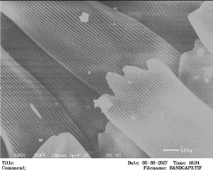
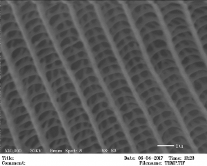
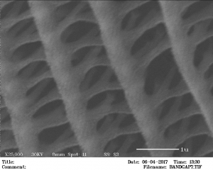
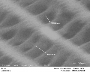
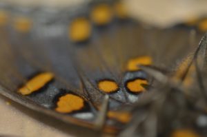
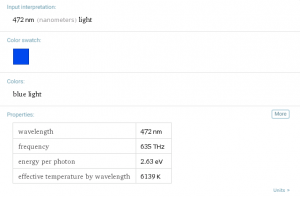
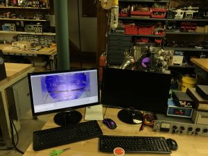
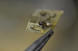
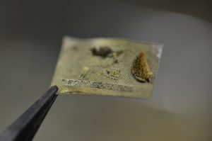
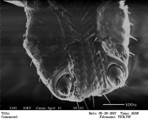
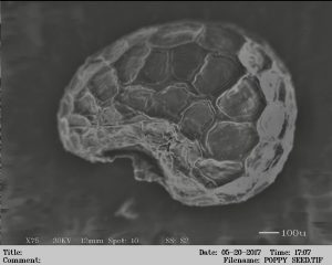
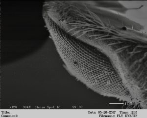
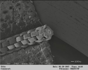
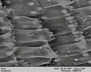
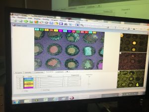
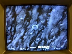
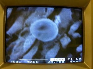
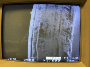
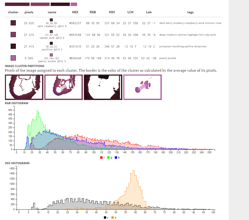
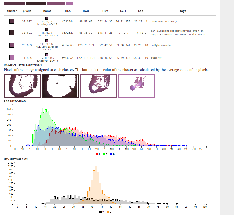
Nano-scale features on butterfly wing scales interact with specific wavelengths of visible light (photonic bandgap material) to produce bright colors as observed by the human eye. This structure, for example, removes certain wavelengths from the white light that hits it (mainly blue, 472nm) so that the color, when observed by the human eye, appears orange.
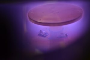
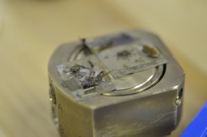
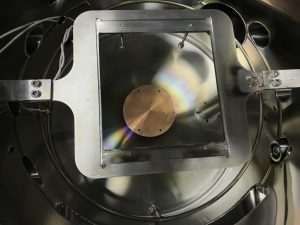
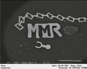
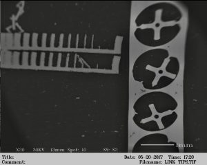
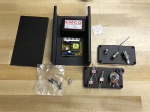
Thin films of copper were prepared on non-conductive samples to be observed under the Electron Microscope. This process is called DC Diode Sputtering and took place at just below 100mTorr and 2000v @ 150watts.
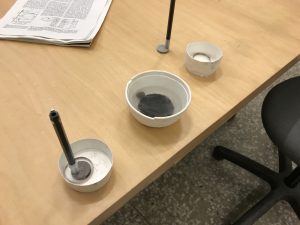
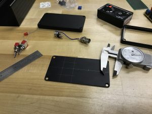
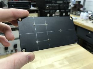
Samples on Conductive Tape
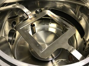
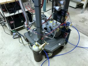
Sputtering Setup v1
Sputtering Setup v1
Sputtering Setup v1
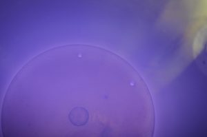
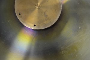
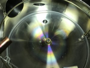
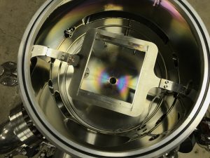
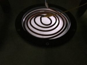
Copper Interference Patterns
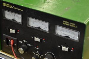
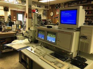
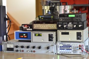
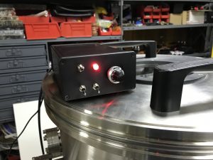
Electrophoresis Power Supply
Sputtered Samples
Sputtered Samples
Sputtered Samples
Unsputtered Samples
This same setup can be used at lower powers to plasma clean or etch the top layer surface of the sample for better images under the SEM. Oxygen (and sometimes a small amount of Nitrogen) is usually a much more effective gas for this cleaning than Argon and leads to less unwanted sputtering as well.
Interference Patterns
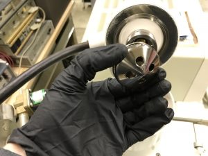
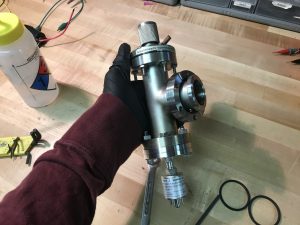
Unwanted Deposition on Feedthrough
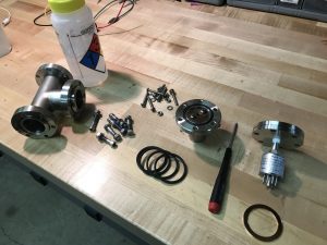
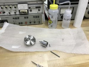
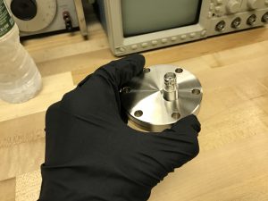
Cleaned Feedthroughs
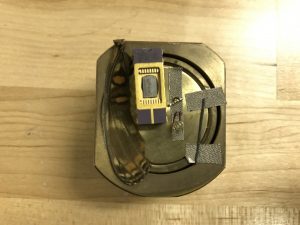
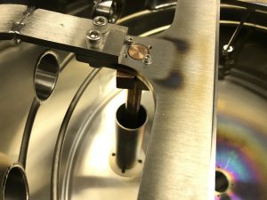
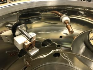
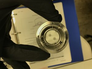
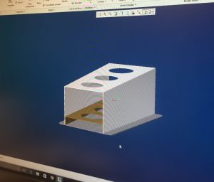
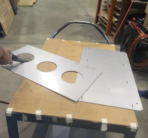
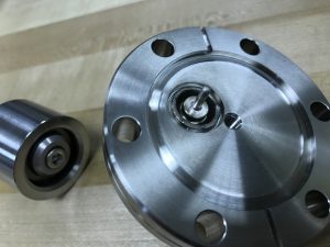
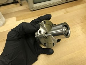
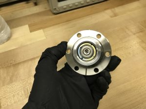
Target Holder
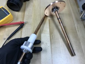
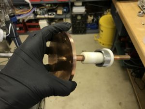
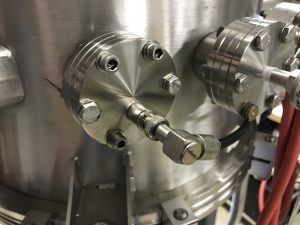
Target Holder Feedthrough
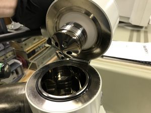
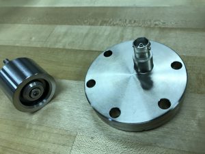
Substrate Pedestal Feedthrough
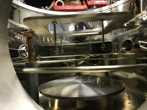
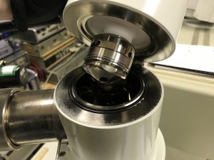
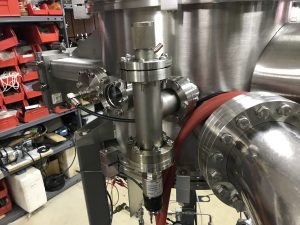
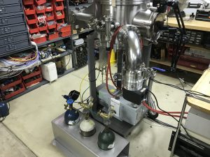
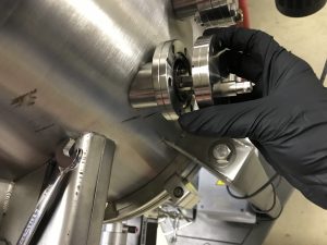
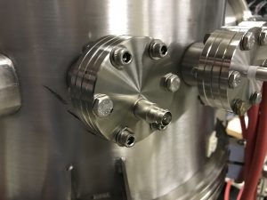
Sputtering Setup v2
Substrate/Bakeout heater
Larger Substrate Pedistol
Sputtering Setup v2
Sputtering system v2 was made to support DC and RF sputtering so I can make dielectric coatings as well and it supports larger target and substrate samples. An insulator will be constructed to mount the target holder to the main chamber walls so that RF can be used more effectively.
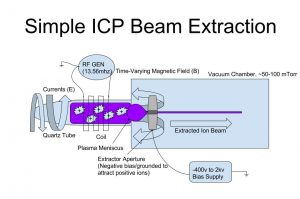
A simple Inductively Coupled Ion Source can be made by using a negative bias on an extractor cone or electrode to attract the positive ions and can later be focused into a beam with magnets. Such a source is suitable at high powers as a Deuteron source for an IEC fusor or for processes such as ion beam deposition or directional plasma cleaning. As seen in Patent #4,793,961, these architectures have been proven for exceptional use as hydrogen or deuterium ion sources.
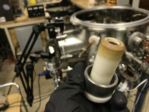
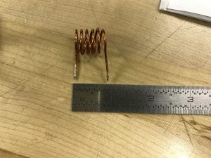
Quartz Tube for ICP
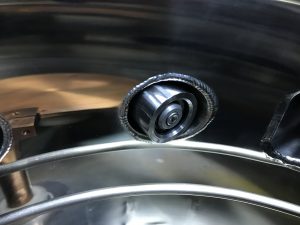
Experimental Setup
Experimental Setup
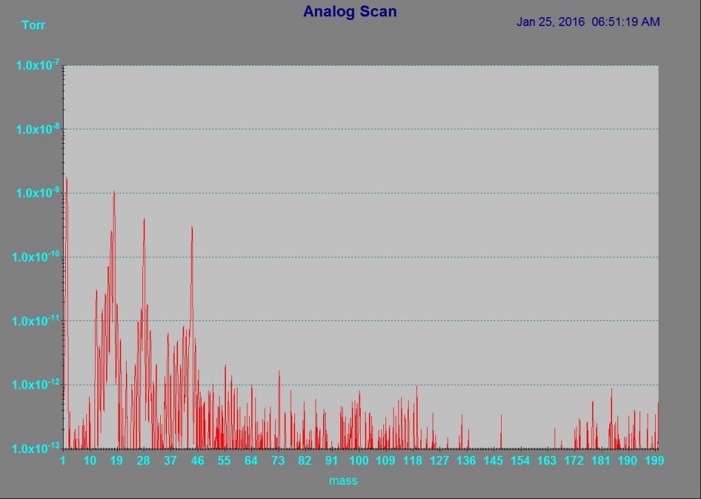
Residual Gas
He Atmosphere
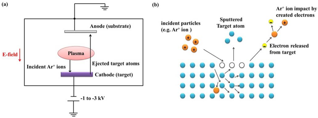
Theory
The ICP coil is placed on a quartz tube mounted via a Kovar KF40 flange to the vacuum chamber and an antenna tuner (matching network) is used to couple the RF energy from 10 meter Ham radio transmitter to the coil. A Multi-cusp Magnetic assembly could be used as shown below to keep energetic electrons from being lost into the ion source walls, confine their motion, and reduce the occurrence of electron-ion recombination.
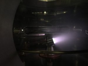
Extractor, -2kv
Extractor, -2kv
Extractor, -2kv
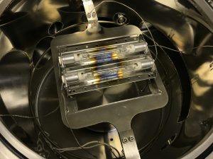
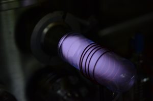
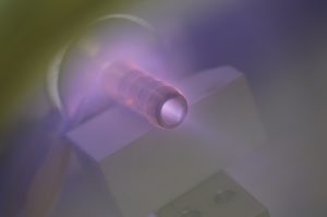
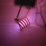
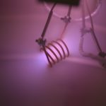
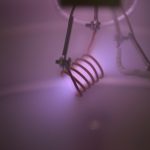
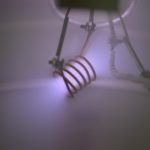
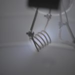
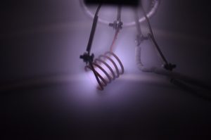
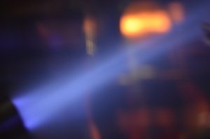
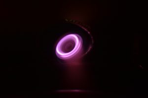
Quartz Tube Fluorescence
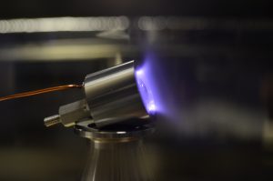
DC Diode Sputtering
DC Diode Sputtering
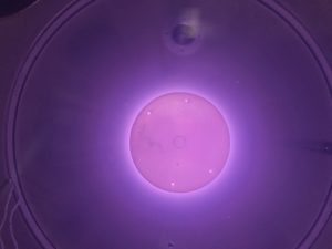
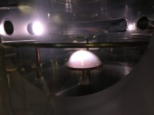
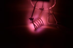
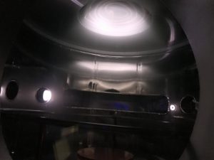
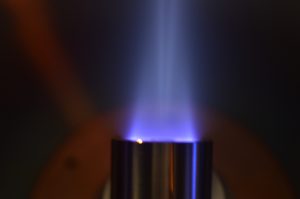
Glow Discharge Anode Glow
Glow Discharge Anode Glow
(Click on image to enlarge)
A high (low) negative voltage (usually between -400v and -2kv) is used on the extractor electrode. If this design was implemented in an IEC fusor, the extractor could be grounded because the fusor grid is held at a negative potential.
Fluorescence was observed in the quartz tube during these experiments due to electron bombardment. While the chamber was pumped down and MFCs setup, a DC copper sputtering environment was created for testing purposes as well as a controlled and isolated anode glow region of an incomplete glow discharge which forms a spherical region above the copper plate (anode) and could be used for uniform plasma cleaning.
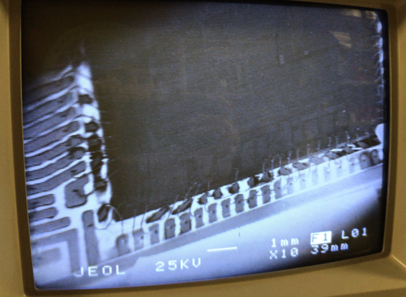
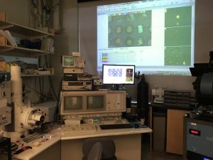
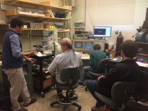
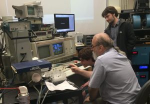
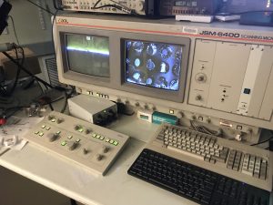
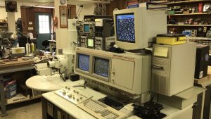
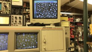
A huge thanks to David Bono from the DMSE UGTL lab at MIT for training me in basic SEM operation during a recent college visit on MIT’s JEOL JSM-6400, which is very similar to my JSM-6300. Because of David Bono and Colin Marcus’s generosity I was able to get my SEM up and running.
Miscellaneous Upgrades – Vent Valve/TC Gauge CF Tee Construction, Gas Cylinder Holder Fabrication, and Ion Gauge Controller Analog Output Hack
ConFlat Components
Completed Tee Assembly
Vent Valve and TC Gauge
Temporary MFC Hookup
Gas Cylinder Holder
Gas Cylinder Holder
Gas Cylinder Holder
Output From Quad Opamp
3.5mm Connector
3.5mm Connector
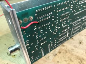
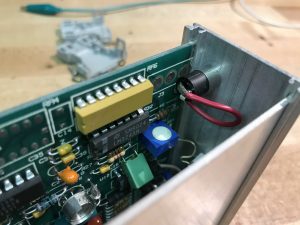
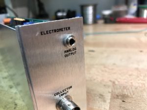
My HP (Granville Phillips) hot cathode ionization gauge controller (59822b) had provisions for an analog output however the optional connector was not installed on the back panel and the connection points on the main PCB of the controller did not show any voltage deflection proportional to pressure so I took the pressure output from one of the stages in the electrometer which happened to be one of the outputs of a quad opamp chip. This output is fed to a NI DAQ USB6009 and displayed in a LabView VI so that the pressure of the chamber while pumping down can be held constant when requested by PID feedback loop with one or more of the mass flow controllers.
A pressurized gas cylinder holder was designed and fabricated by Diversatech Manufacturing, INC (www.diversatech.com) for safer operation of my vacuum chamber when using gasses such as Oxygen, Nitrogen, or Argon for processes such as sputtering or plasma cleaning.
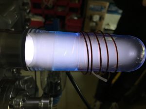
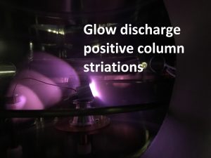
Due to different gasses pumping out of chambers at different rates (i.e. Hydrogen always has a low pumping speed) and air’s natural composition changing glow discharge colors can be observed while pumping down a vacuum chamber. This was an attempt to estimate the pressure of the chamber indirectly during a pump down by observing and analyzing the inductively coupled plasma color at constant RF voltage.
Inductively coupled plasma (ICP) is a common method of ionizing the residual gas in a vacuum chamber. A RF source (commonly 13.56mhz) is connected to a coil (usually outside of the chamber) which induces currents in the nearby gas volume because of the time-varying magnetic fields.
I used a 10 meter (28mhz) 100 watt ham radio transmitter at 60mTorr with multiple coil designs to create an inductively coupled plasma. Even while minimizing the reflected power with a matching network (antenna tuner) the plasma was difficult to ignite. By briefly powering an anode layer ion source in proximity to the ICP coil I was able to ignite and sustain the ICP at lower power levels.
Once the ICP is sustained, the ALIS is powered off and the RF ICP remains on.
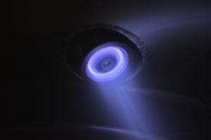
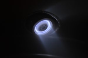
Tests were run at 50millitorr and between 800-1000v. Air plasma can been seen as low as 300v. Typical current at 1kv is 4ma. When the source is current limited, you can see a de-focusing effect as seen in the 2nd picture. This is because the ion source is not operating through the closed drift mechanism but is rather operating closer to a modified glow discharge under the influence of a local magnetic field.
Above pictures taken at much lower pressure and higher voltage (5e-4 torr and 4kv+)
ALIS mounted on 2.75″ CF flange via 10-32 standoff and electrical connection via MHV connector. As suggested and fabricated by J.D Guerard machining Co., a ditch was formed around the hole drilled for MHV feedthrough on the interior side of the flange which created a wall matching in thickness to the MHV connector feedthrough to facilitate with fusing. This can be seen in the first picture. When welded, the two surfaces of identical thickness are fused together easier, with lower current (this weld was done at only 20amps), and with consequently with no warping of the entire flange because of the localized heat.
Residual Gas – 1e-3Torr
Residual Gas – 1e-4Torr
Residual Gas 5e-4Torr
Helium – 100mTorr
Using the anode layer ion source as a crude ion pump (far from ideal conditions, stainless steel chamber walls do not have high getter/sputter capacity)
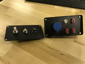
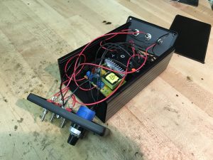
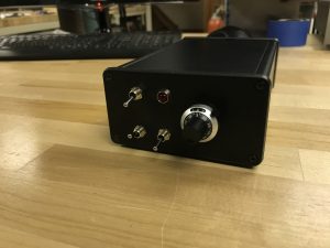
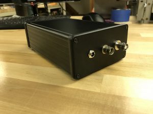
I made this dual high voltage power supply for an ion source (0-4kv) and also to bias the collector in a Faraday cup to remove secondary electrons from measurement (0-350v, typically 90v). There are 2 boost converters for the high voltage and one buck converter to power the 0-4kv boost, which is an Emco F40. It can provide 4kv @ 2ma and is connected to the MHV connector on the back panel. The Faraday Cup bias supply outputs through the BNC, and the main power connector is a 12v in through the barrel jack. There is a 10 turn potentiometer on the front panel with locking knob for precise adjustment of the high voltage.