Lithography Projector Mod – Color Wheel Removal

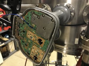
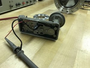
When modifying a projector for photolithography, one thing to note is the UV transmission quality of the optics. Often, the stock color wheel in most DLP projects attenuates that UV significantly on the clear and blue sections. Thus, it is beneficial to remove it however the projector has RPM feedback (from motor back-EMF and/or photodiode) so simply removing it will result in the projector not starting up. A simple RC relaxation circuit can be built to emulate this signal (often 60 or 120hz) so that the projector will function properly.

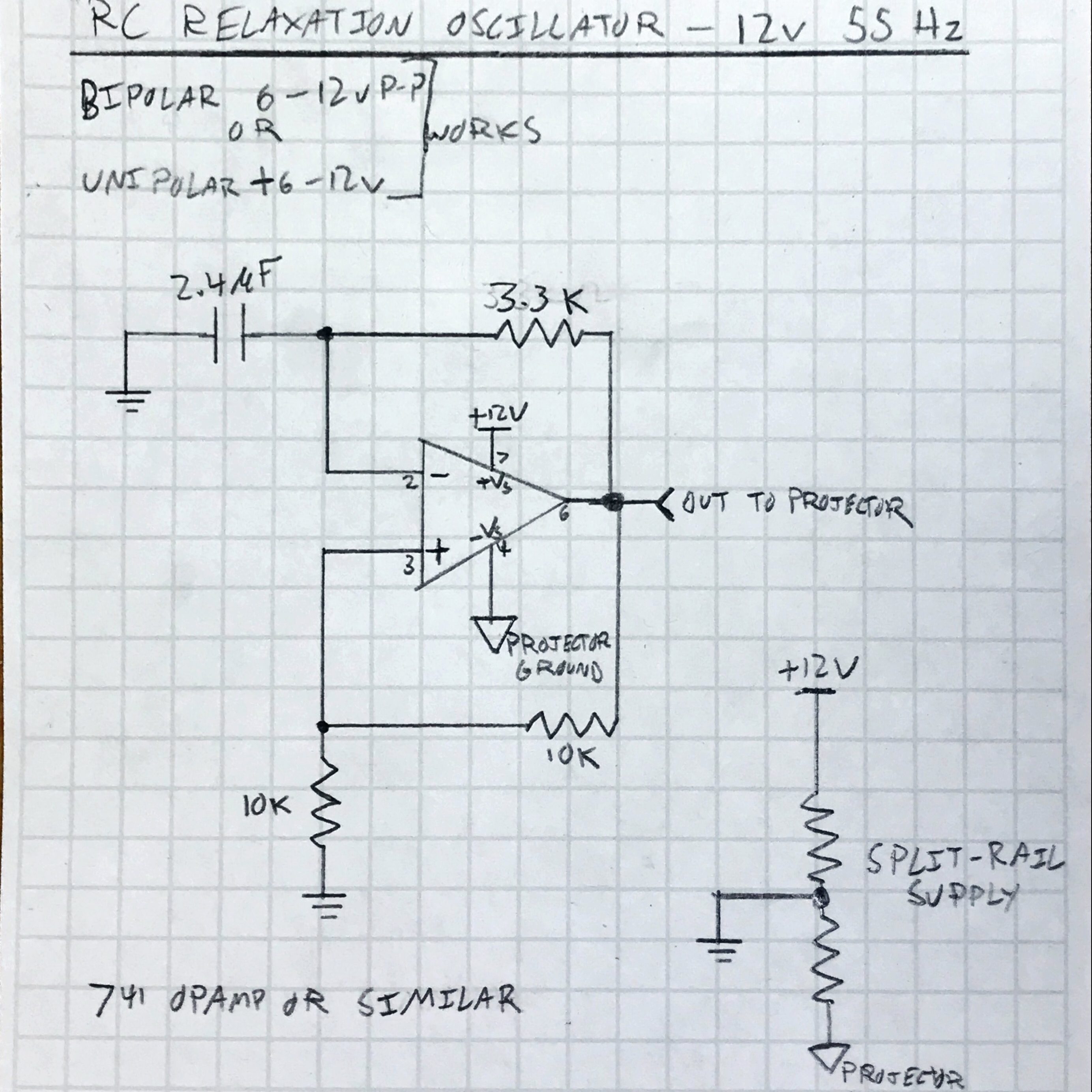
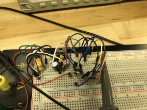
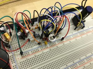
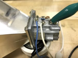
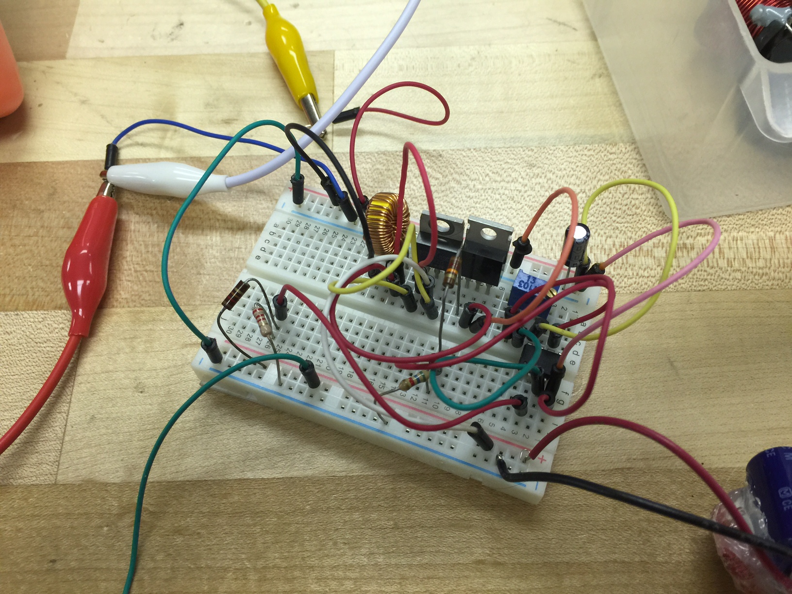
The circuit shown below is approximate. The 2.4uF capacitor and 3.3KΩ resistor set the frequency of oscillation.

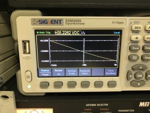
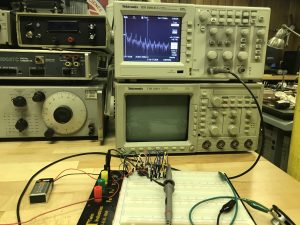
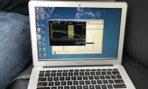
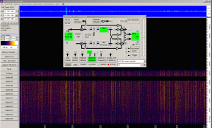
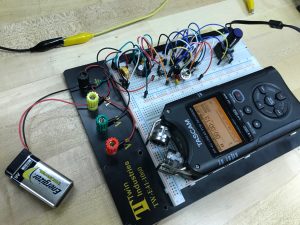
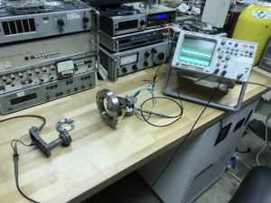
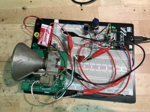
The completed circuit is probed and verified using an oscilloscope, using channels 1 and 2 which display the oscillator output and capacitor charging waveforms, respectively, in the last photo.

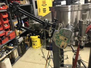
In the end, the projector is “fooled” into operating with monochrome light output without a color wheel.

Maker Faire NYC 2017

News features:

36640684863_05b25e1d8c_k

Maker Faire Project Page

Granville-Phillips Micro Ion Gauge ATM Repair

The Micro Ion Gauge ATM is an awesome gauge that is extremely sensitive and reads from atmospheric pressure down to 1e-9 torr switching seamlessly through a range of 4 different vacuum gauges. It has an analog voltage output from 7volts down to 0.5v logarithmic to the pressure. This gauge had very bad noise issues, the voltage output moved with pressure change but was not useable due to the analog output swinging ~ +/- 0.25 volts multiple times per second.

The problem was found to be bad electrolytic caps, as expected. They exhibited high ESR, Low DC resistance, puffed up vent/tops, and electrolyte leakage on the PCB.

Prototype VLF/ELF Receiver Frontend Testing

Live VLF Stream

Quick prototype of a VLF/ELF receiver with two stage low noise amplifier and passive RC bandpass filtering. First stage has a gain of 180 then is fed to a lowpass and highpass filter then to another opamp with adjustable gain up to 500. Resulting signal is sent to a Focusrite Scarlet i2i 24bit USB audio interface and sampled at 192KHz.

This simple preamplifier can easily pick out the “fire crackling” of lightning strikes around the world form the noise floor and can easily resolve other natural low frequency radio phenomena such as “”whistlers”. Active bandpass filtering and 60Hz notch filter will be added as well as a shielding enclosure and low noise Analog Devices OP270 or similar opamps will be used in another iteration of the design.

Antenna used was two large screw drivers inserted into the ground soil separated by about 50 feet in the woods 1/4 mile from any house or power lines. 60Hz noise was exceptionally low considering only passive RC filtering was used which has high and low -3dB points far away from what you actually design the cutoff frequencies of the filter to be.

This frontend contained no input protection in the form of glow discharge neon lamp, clamping diodes, thermistor, MOV, fuse, etc. Next design will incorporate multiple such devices however it is not a great priority for testing because I am using the screwdriver ground probes for antenna which is less susceptible to high voltage buildup in storms as a whip or dipole antenna.

http://www.vlf.it/

Microwave Plasma Interferometer Prototyping

(Click on image to enlarge)

Prototyping of a microwave interferometer setup has begun using modified police radar and satellite television parts, namely Gunn Diode oscillators (gunnplexer) and LNBs with dielectric resonant oscillators as well as PLL synthesized ones. Tests are being conducted at X, Ku, and K bands. The goal of this is to non-intrusively measure electron density in plasmas in my chamber. Results of these experiments will be posted.

Ion Source and Faraday Cup Biasing Power Supply (dual 0-350v and 0-4000v)

I made this dual high voltage power supply for an ion source (0-4kv) and also to bias the collector in a Faraday cup to remove secondary electrons from measurement (0-350v, typically 90v). There are 2 boost converters for the high voltage and one buck converter to power the 0-4kv boost, which is an Emco F40. It can provide 4kv @ 2ma and is connected to the MHV connector on the back panel. The Faraday Cup bias supply outputs through the BNC, and the main power connector is a 12v in through the barrel jack. There is a 10 turn potentiometer on the front panel with locking knob for precise adjustment of the high voltage.

IMG_0124 IMG_0125


Spellman High Voltage Reference Manual

6mhz TTL Oscillator Used as Quartz Microbalance


A 6mhz oscillator can was cut up with pliers and the top was removed to expose the quartz crystal. The output is AC coupled (high pass filtered) to the positive (+5v) rail so that a single coax cable can be used to connect this to the thickness monitor as the power is basically just a DC offset on the signal. If you buy a pack of crystals from somewhere like Lesker they will (depending on your thickness monitor) most likely require the usage of an external oscillator. Such a circuit can be made by a complimentary pair or NPN and PNP transistors and couple passive components. Thanks to Ben from Applied Science for the idea.

Abstract: The quartz microbalance is a quick way of monitoring thin film thicknesses in real time, a bare quartz crystal which oscillates at a known frequency is placed in the chamber near the substrate involved in deposition. As the film accumulates on the crystal, it gains mass and the resonant frequency is lowered. The cumulative frequency change is analyzed and interpreted as the rate of accumulation the rate is integrated into a total thickness. Note that accumulation rate is the proper term for deposition rate, as in many cases (sputtering) the actual deposition rate is higher but some atoms are resputtered off the substrate due to high energy molecules in the chamber, substrate temperature, etc. and the total film thickness can momentarily decrease. The net result of the deposition and resputtering is known as accumulation

FullSizeRender

+/- 0.1nm resolution!

Switch Mode Power Supply Design + laser cut/etched PCB

IMG_7582 IMG_7560 IMG_7559 IMG_7321 IMG_7319
IMG_6244

Buck/Boost converter design for a solar glider I was working on last summer, at 16v it reached 98% peak efficiency and 95% average in boost mode. Also tried to make a linear power supply board using a laser engraver to cut away the copper, it worked pretty well to replace the normal ferric chloride etch step. Continue reading Switch Mode Power Supply Design + laser cut/etched PCB