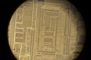
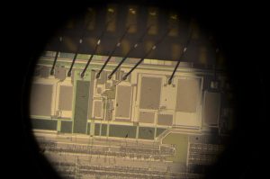
Oxide and Spin on Diffusant Thin Film Interference Patterns on Wafers

spin on diffusant interference patterns 4 spin on diffusant interference patterns 3 spin on diffusant interference patterns 2

spin on diffusant interference patterns 1 large wafer contamination from thermal oxide growth structure stress patterns

As of now, I am doing all of my doping with spin on diffusants. Some of which are solutions of Phosphoric/boric acid in alcohol/water that I prepared myself. I find it hard to control the dopant concentration and therefore bandgap of devices so my solar cells often have a bandgap too high or too low. I thought using an actual spin on dopant would help, so I bought some P509 phosphorus glass from Filmtronics and it works about the same as the solutions I made, except it spins on much nicer.

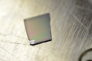
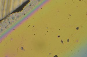
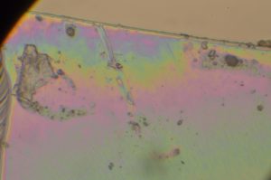
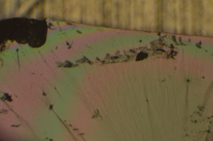
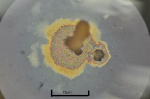
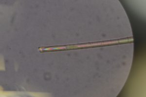
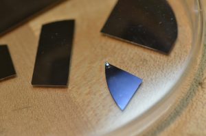
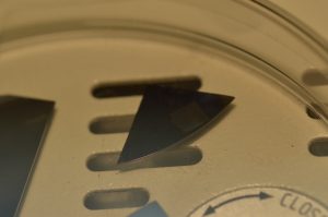
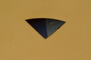
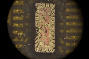
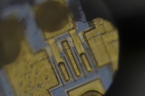
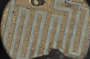
The colors you are seeing are contamination and nonuniformity in the thin film interference patterns caused by this thin glass layer after pre deposition of the spin on diffusants.

Continue reading Oxide and Spin on Diffusant Thin Film Interference Patterns on Wafers
Silicon Wafer Pics – Thermal Oxidation

50mm wafers 3 Copper 8_ wafer


moisture on 50mm wafer 500nm oxidation macro50mm wafer 500nm oxidation macro(5)

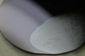
Blue color indicates roughly 500nm SiO2 thickness. It took about 2.5hours to grow @ 1200c in a pottery kiln style furnace with steam being pumped into it. Picture above on the left shows moisture on cooling wafer. Picture on the right shows unpolished backside of the wafer. Notice the nonuniformity in the growth thickness caused by unequal heating. This is because I don’t have a quartz boat to hold the wafers so I place them face up in the furnace.  Continue reading Silicon Wafer Pics – Thermal Oxidation

Homemade Photovoltaics – DIY Silicon PN Junction Solar Cell Testing

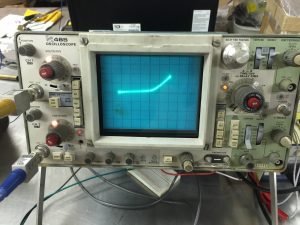
Testing of homemade solar cells/PN junction diodes. Some of them output up to .25v open circuit and a few hundred microamps at short. This varies widely because of changes in dopant concentration and wafer size. The higher dopant concentration makes a lower bandgap. Most of these devices have a band gap that is too low to be most efficient for a solar cell. Optimally I would want about 1.4ev. As dopant concentration increases, the wave functions that describe the electrons in both valence and conduction bands start to converge and overlap so the bandgap basically gets broken and the solar cells preform very poorly. I estimate about 1% efficiency on these cells, most likely less.

Silicon Wafer Low Temp Anodic Oxidation Attempt in Aqueous Potassium Nitrate Solution

https://www.youtube.com/watch?v=KgTqeUk6XS8

I wanted to try anodic oxidation because it would allow me to grow SiO2 dielectric layers much quicker and also at room temperature. The result, while using potassium nitrate solution, was a very dirty growth later that would only be suited for a field oxide on a diode and far from precise enough for a gate oxide on a FET. Possibly with more refining in the future this could save me a lot of time waiting for furnaces to heat up.

Cleaving a Large Silicon Wafer

https://www.youtube.com/watch?v=Su6-Bl29cEM

This wafer has an un patterned copper metalization layer.

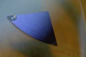
Monocrystalline wafers with a known crystal orientation (<100> in this case) can be easily cleaved into small squares (or triangles, depending on the orientation). Traditionally, <100> wafers are used for CMOS/FET devices and <111> wafers are used for bipolar devices. Thermal oxidation, SiO2 etching, and carrier mobility can greatly differ based on orientation. I believe 100 wafers have lower hole mobility than <110> and <111>. <111> wafers have the highest packing density.  <100> wafers allow field effect devices to have lower threshold voltages. Many MEMS devices use <110> or <111> wafers.

Growing Thermal Silicon Dioxide on Silicon Wafer

I had the day off school due to a bomb threat so I had some extra time to work in the shop and had my first success with thermally grown SiO2. The process is very simple. At the time, I didn’t have a tube furnace so I put the wafers in a pottery kiln that went up to 1000c and poured 25ml of water into the top of the kiln through a small opening manually every 5 minutes for about 6 hours to saturate the furnace with water vapor. This wet oxidation technique allowed me to grow the field oxide for my first few semiconductor devices, diodes.