Superconductor Sputtering Chamber

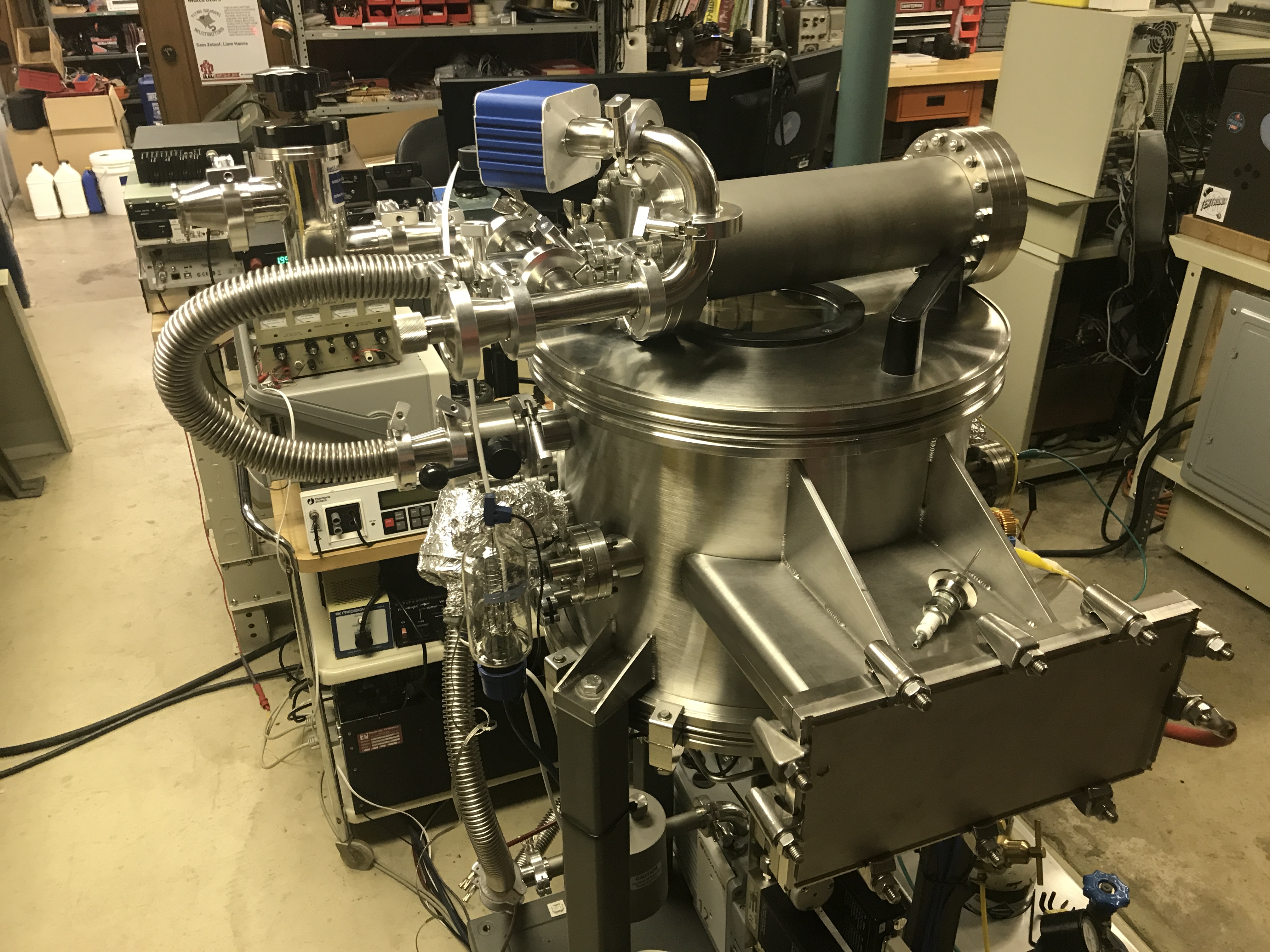
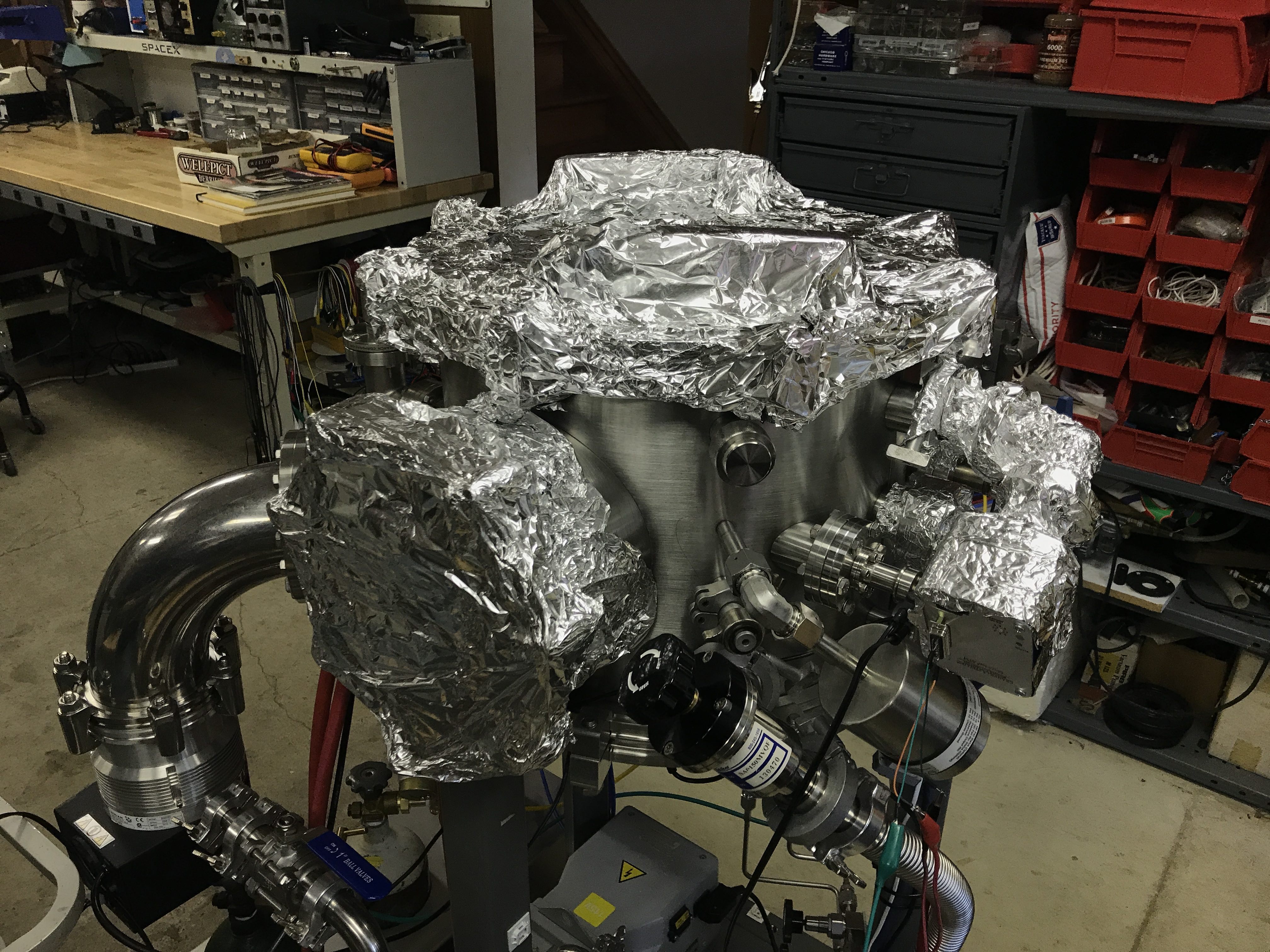
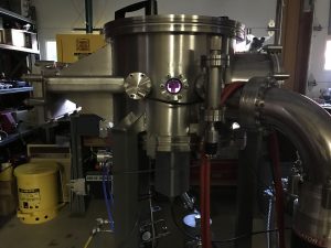
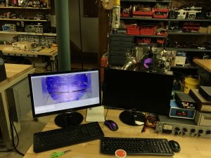
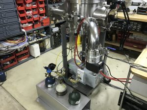
This project involved developing a sputtering system in collaboration with Ilya Drozdov in the Oxide Molecular Beam Epitaxy / Condensed Matter Physics Group at the Brookhaven National Laboratory. This system has 2 process gas feeds, an infrared substrate heater, and is designed for low-rate coatings that last 2 weeks each.

You can see other services that I offer here

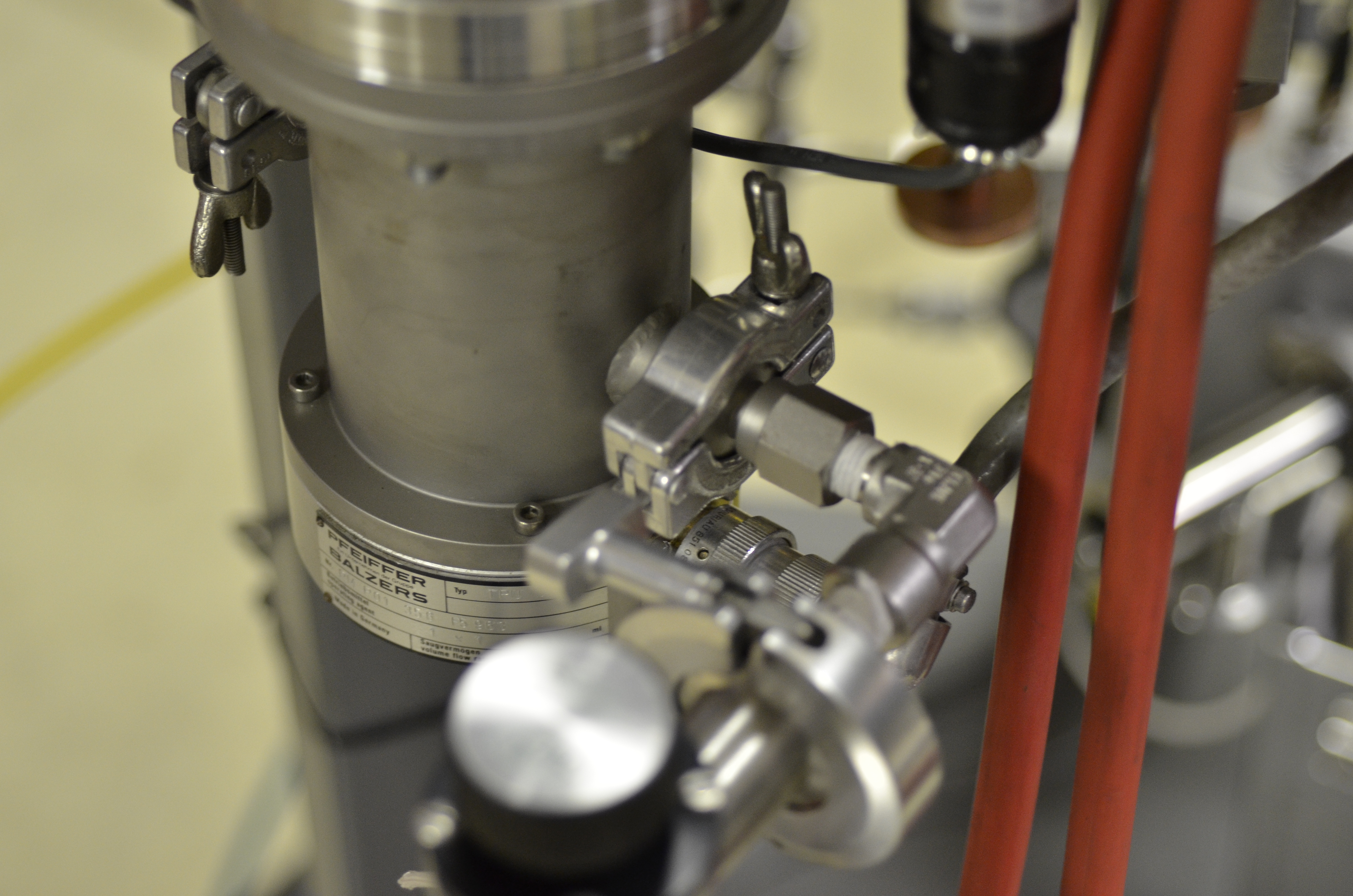
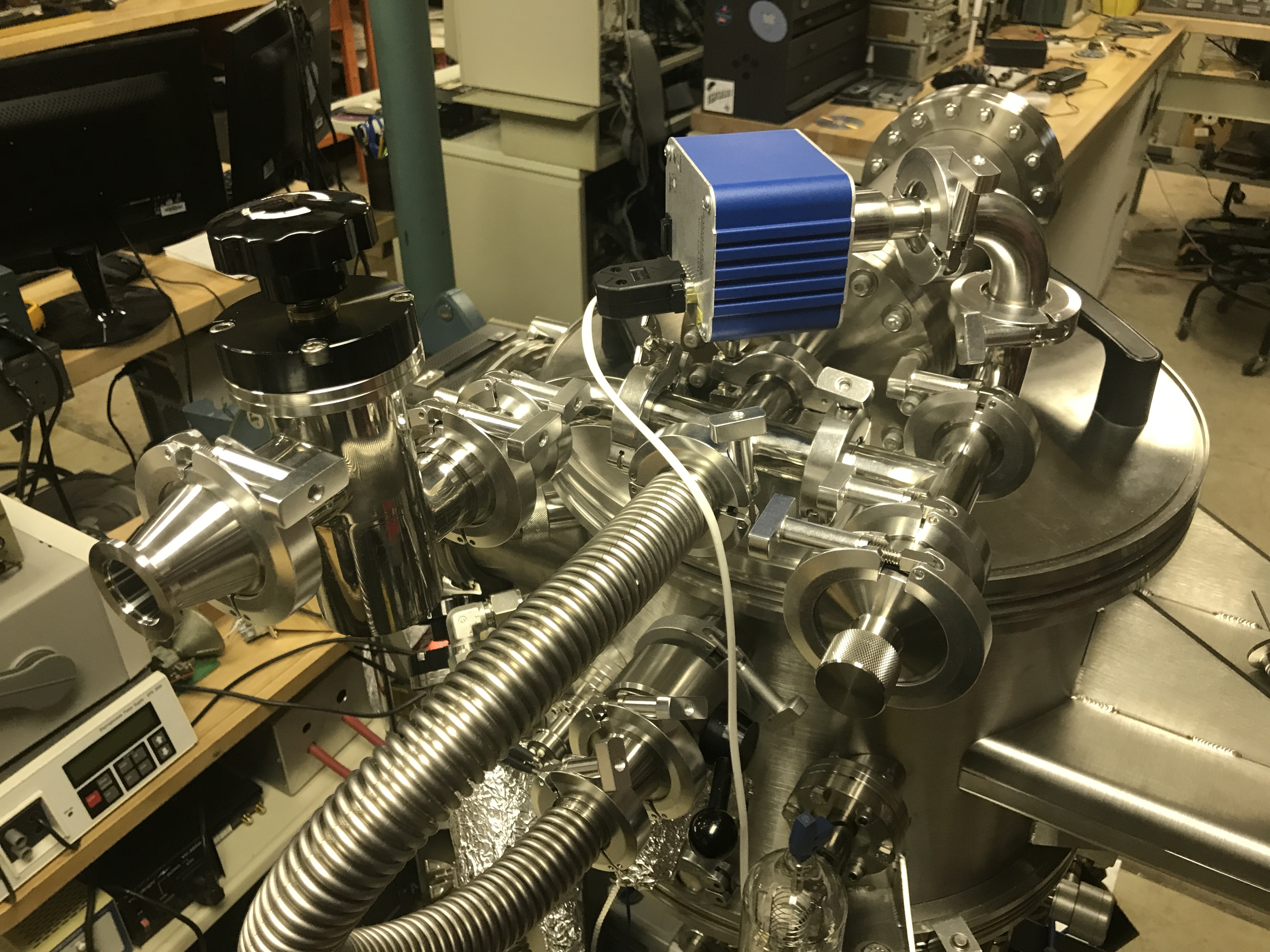
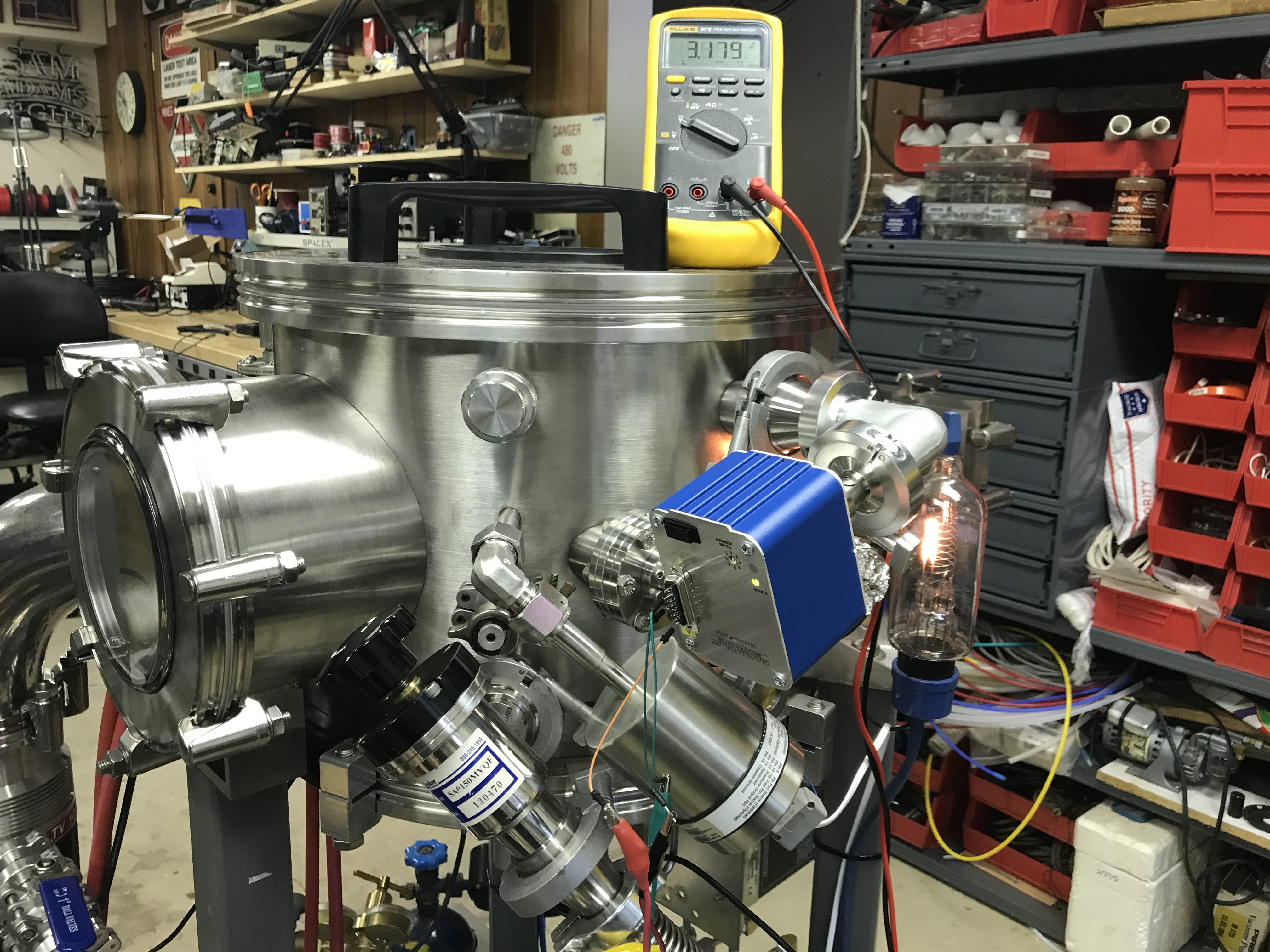
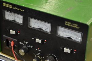
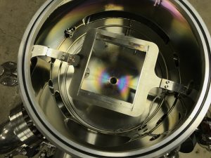
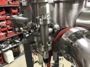
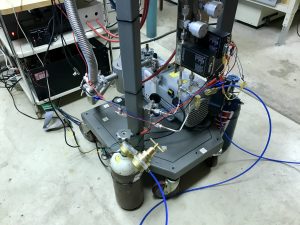
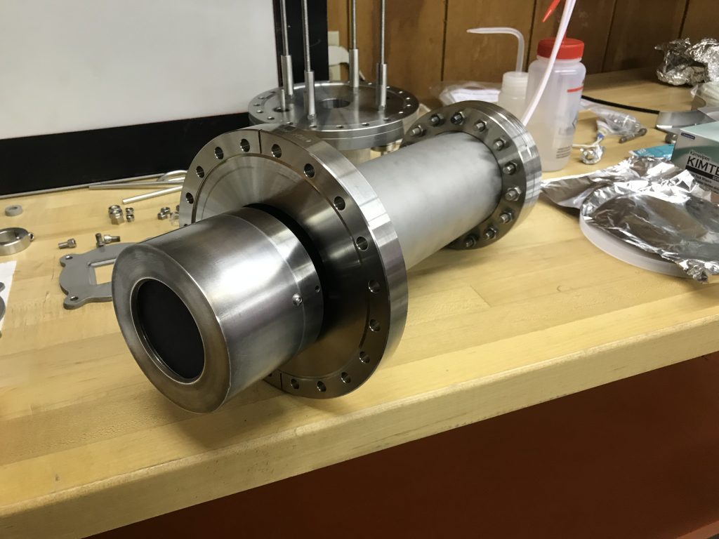
The vacuum system consists of a large dual turbo pump (510L/s) backed by a scroll pump and throttled with an 8″ VAT gate valve. The process requires O2 and Ar lines on Mass Flow Controllers plumbed in as well. The MKS controller drives the MFCs to flow in the process gasses in the correct ratios and keep the pressure within 1% of the setpoint.

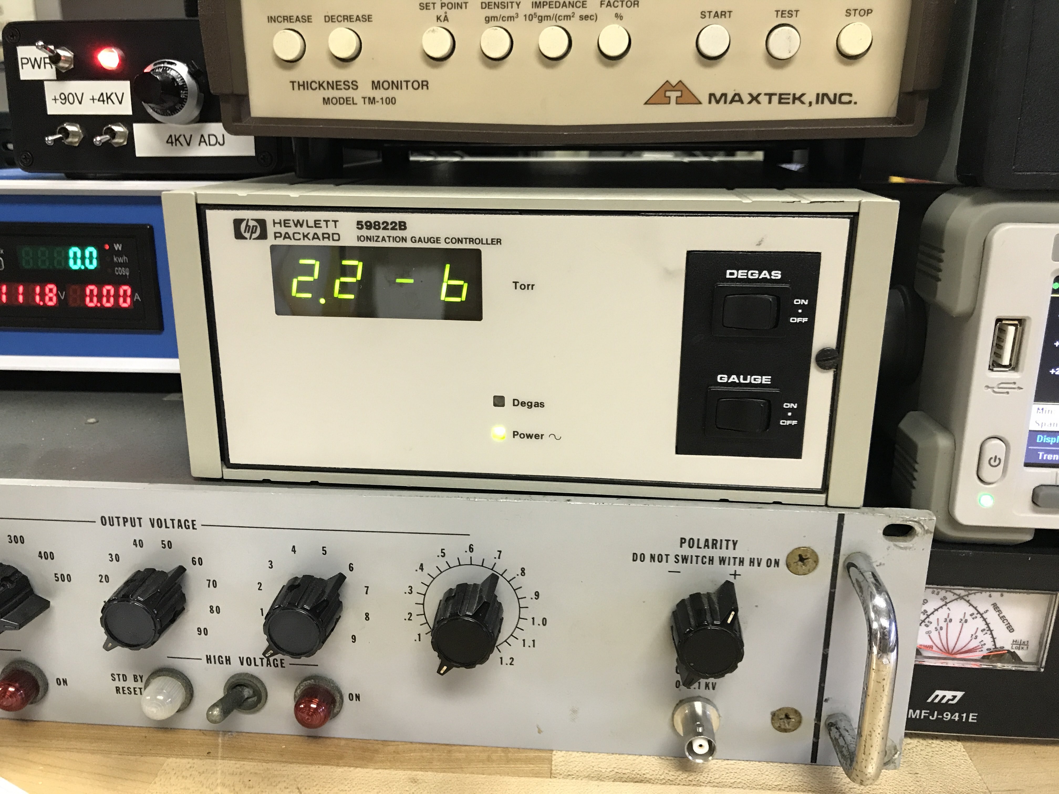
The chamber is quickly evacuated to the 1e-7 Torr range although the actual process occurs around 50 – 100mTorr under O2/Ar atmosphere.

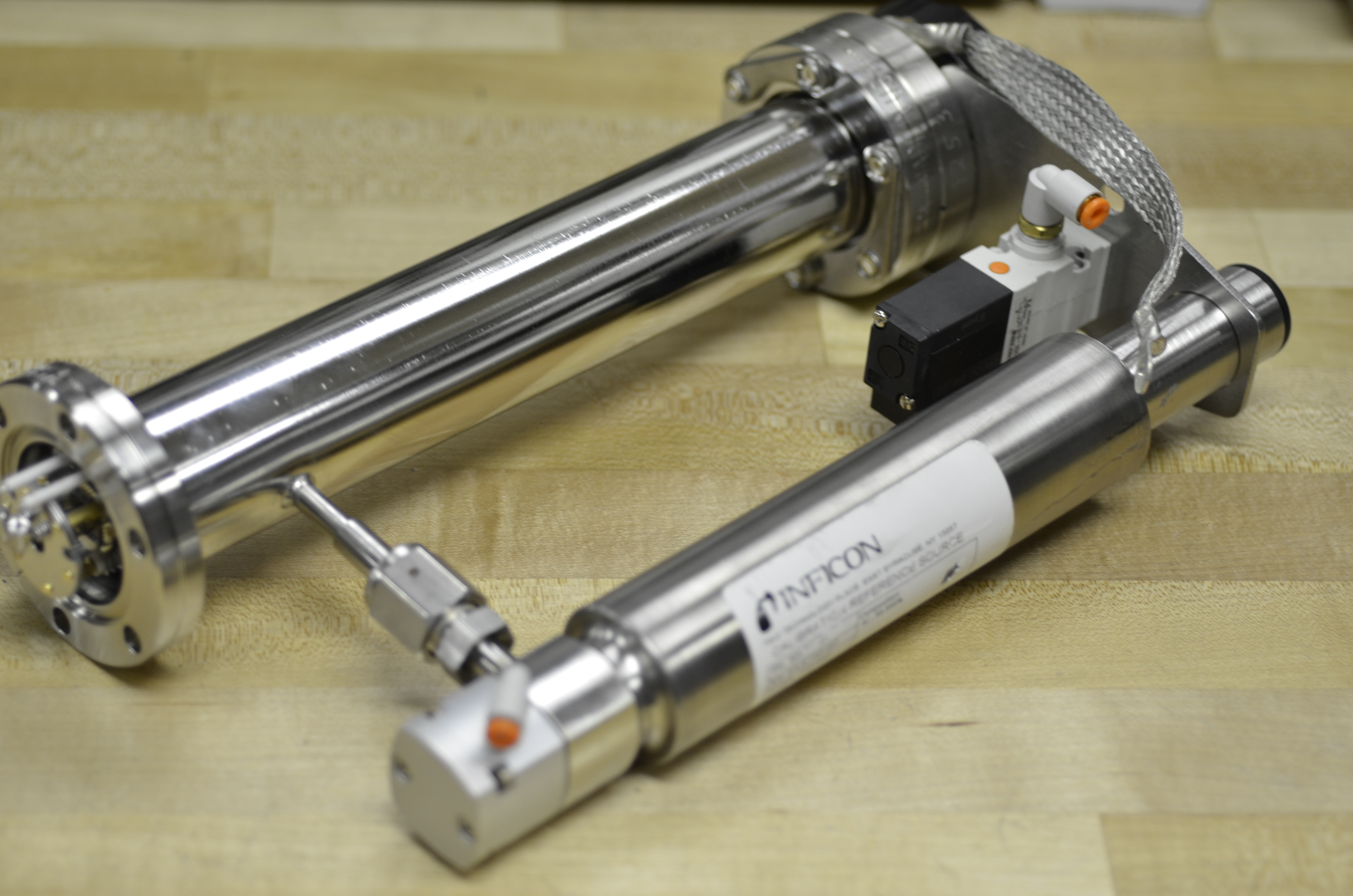
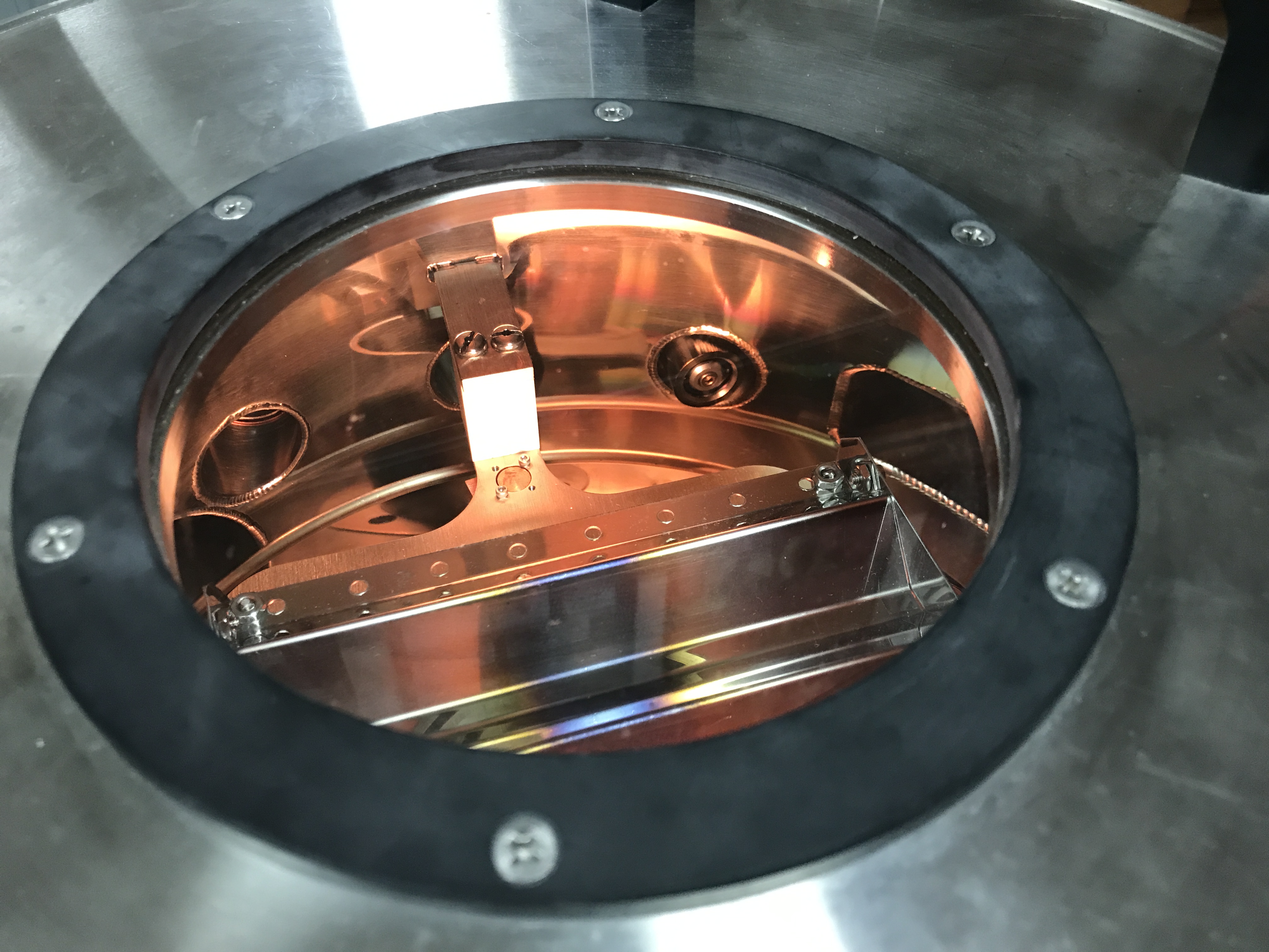
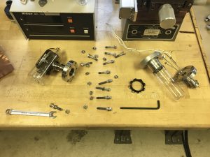
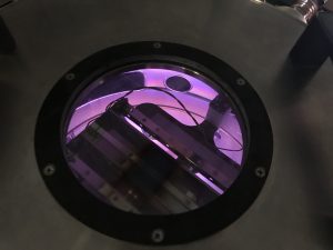
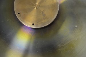
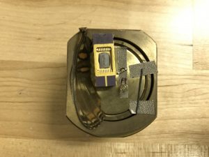
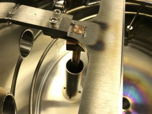
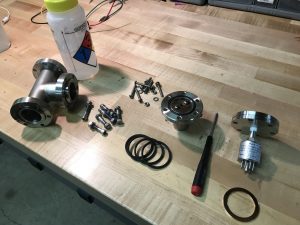
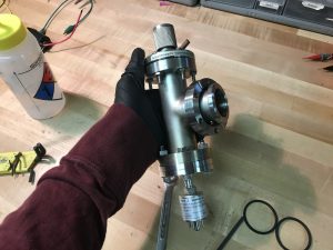
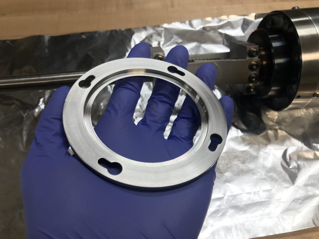
The 3″ dia. sputter gun was salvaged from combining old stock of broken ones together and making one functioning sputter gun.

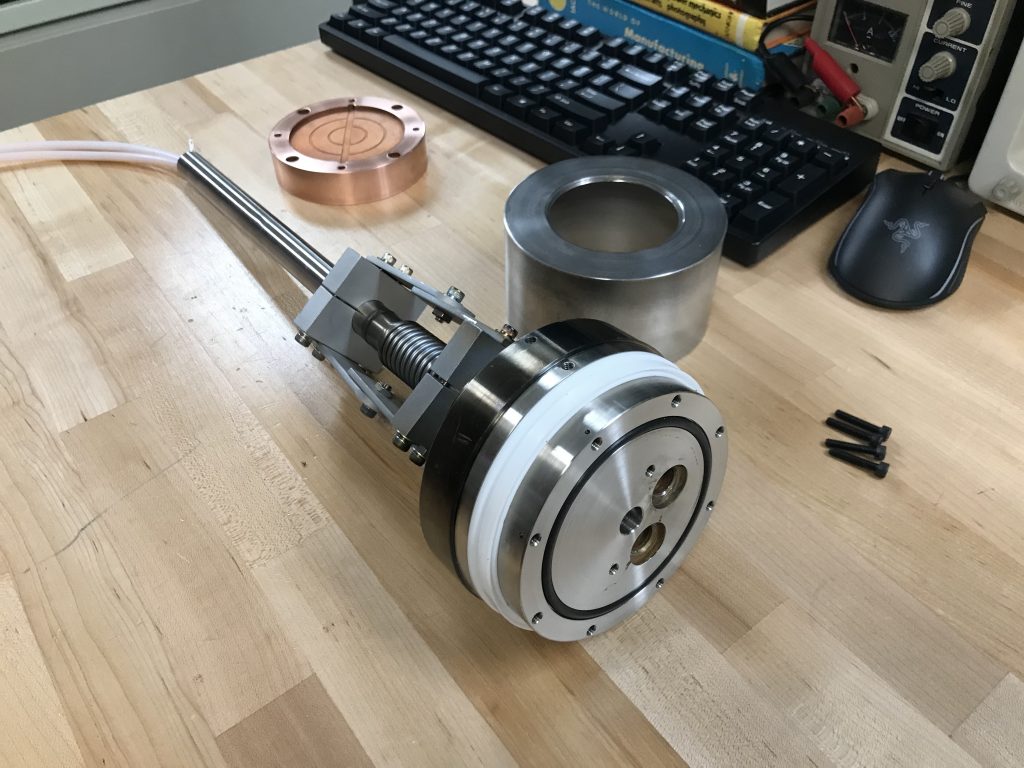
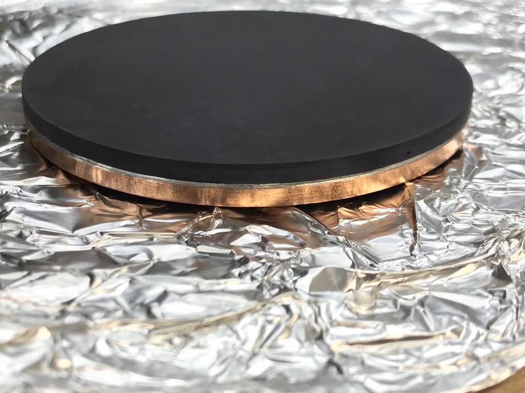
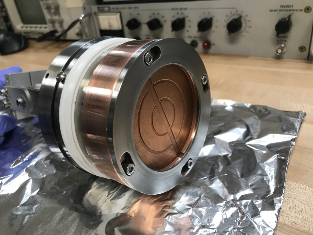
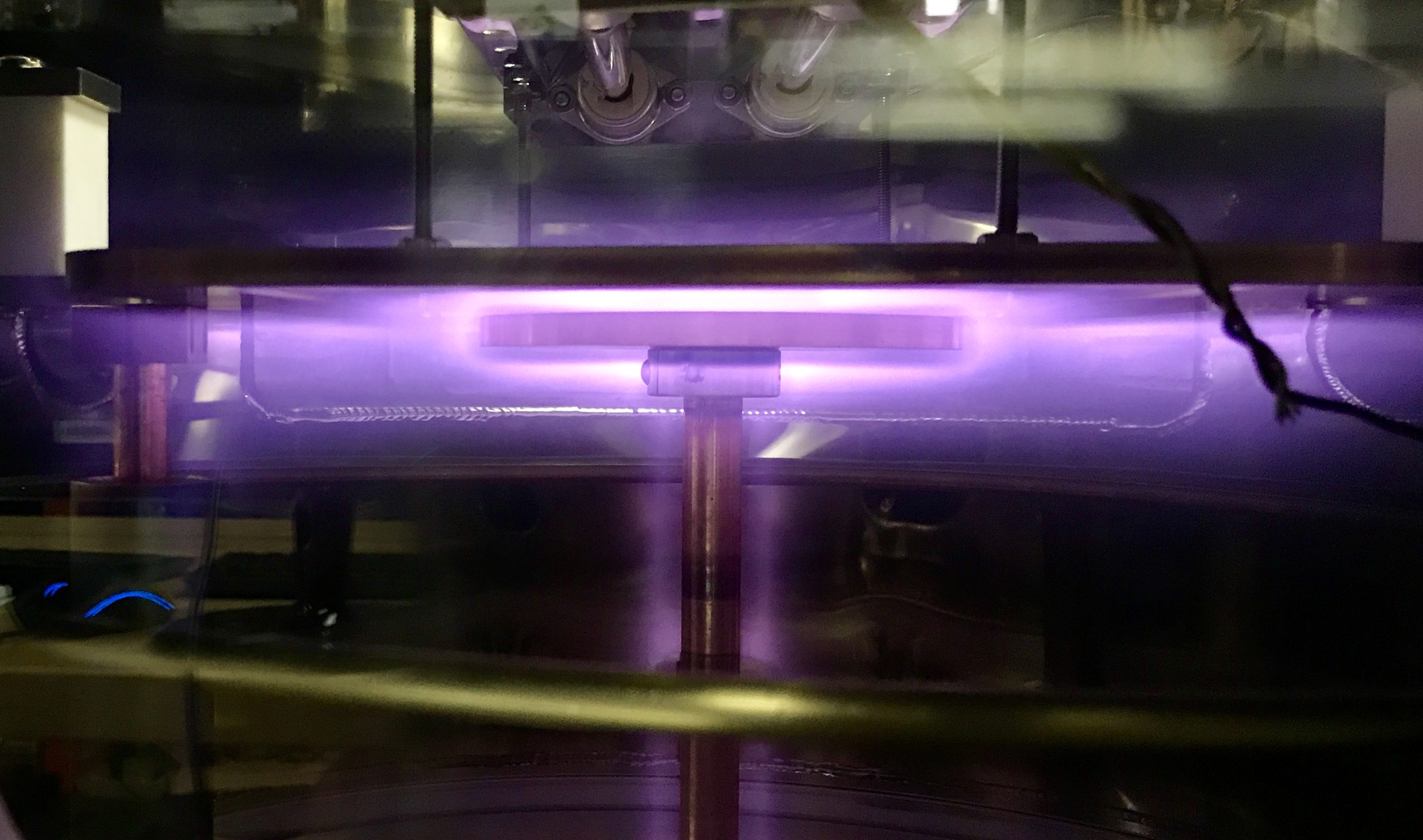
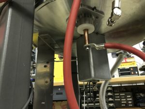
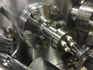
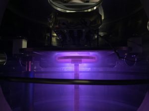
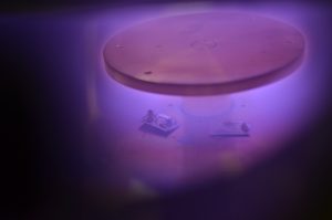
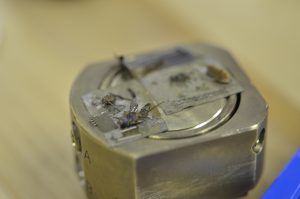
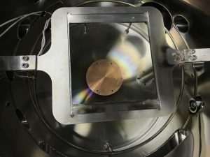
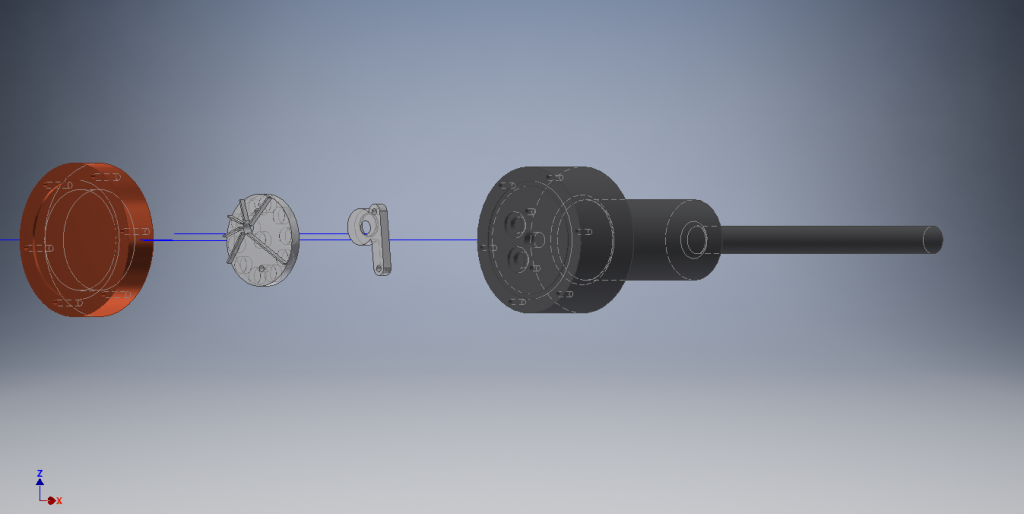
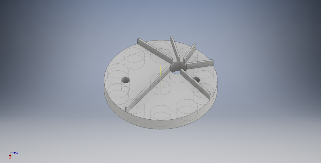
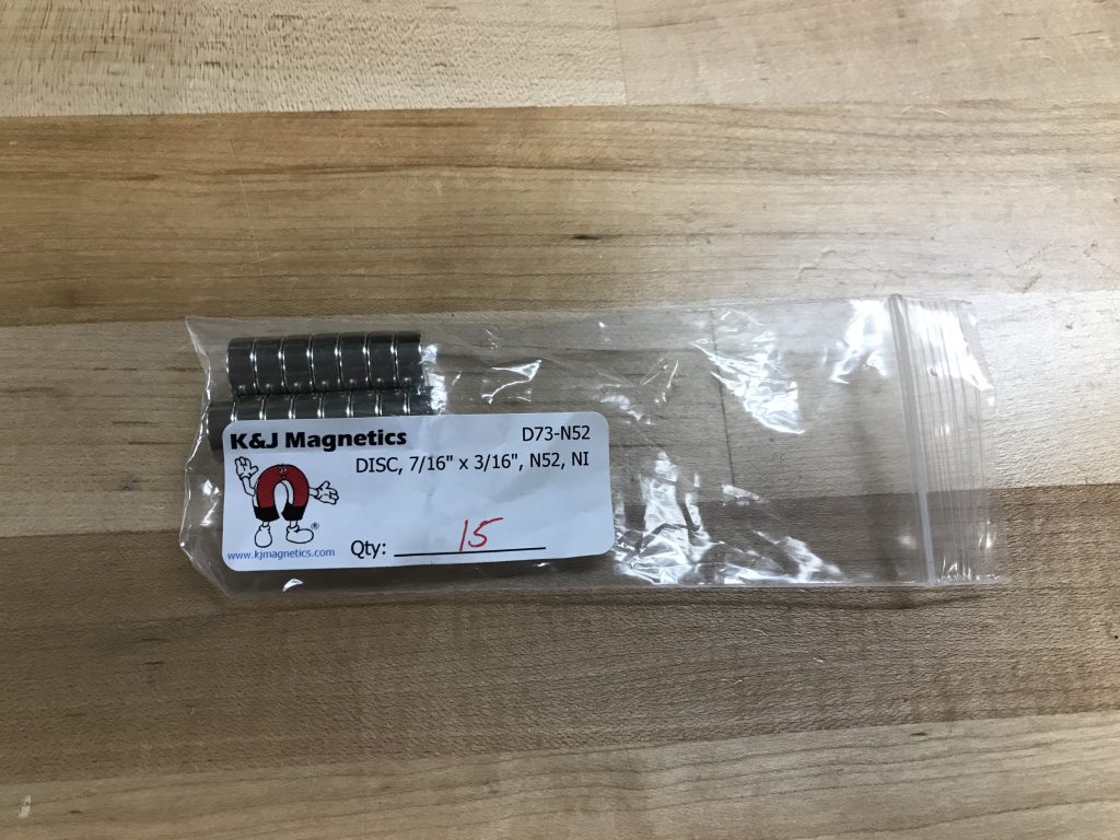
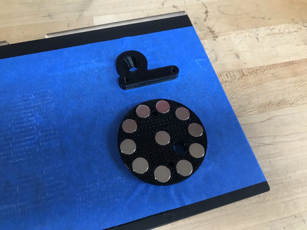
The sputter target is clamped to the Copper puck which is water cooled because of the high power involved in these sputtering processes. All of the sputter gun parts I started with had rusted magnet assemblies, so I had to make a new one. A 3D printed puck that fits inside the copper piece was designed with embedded rare Earth magnets to create a surface DC field of around 400 Gauss which confines electron movement and induces the magnetron effect.

TOP 246_back

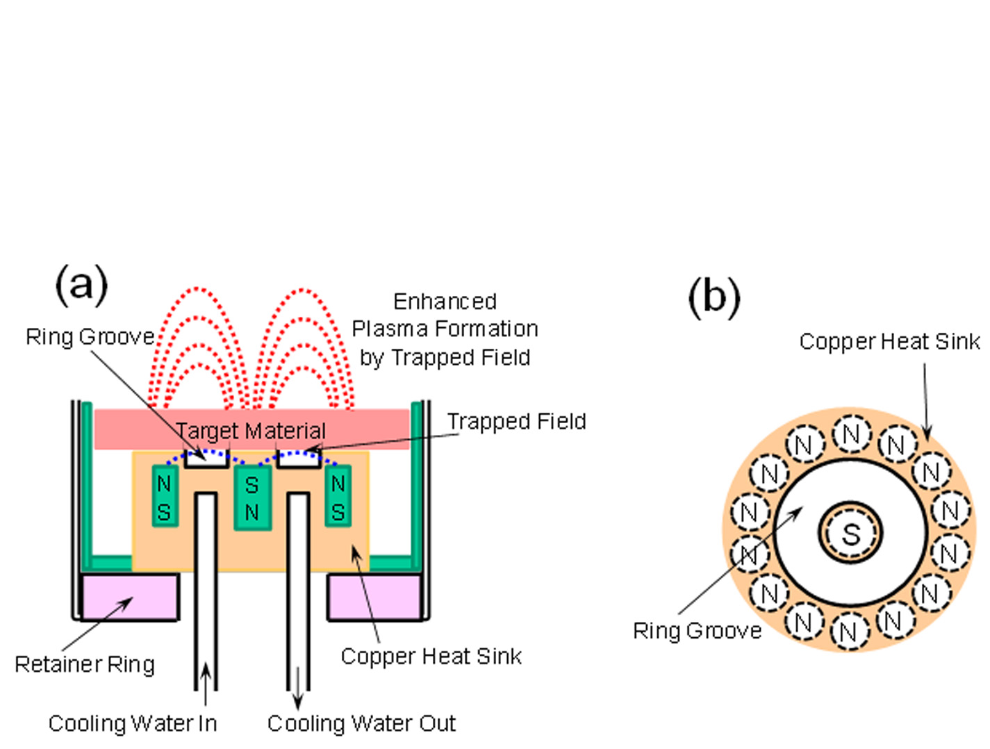
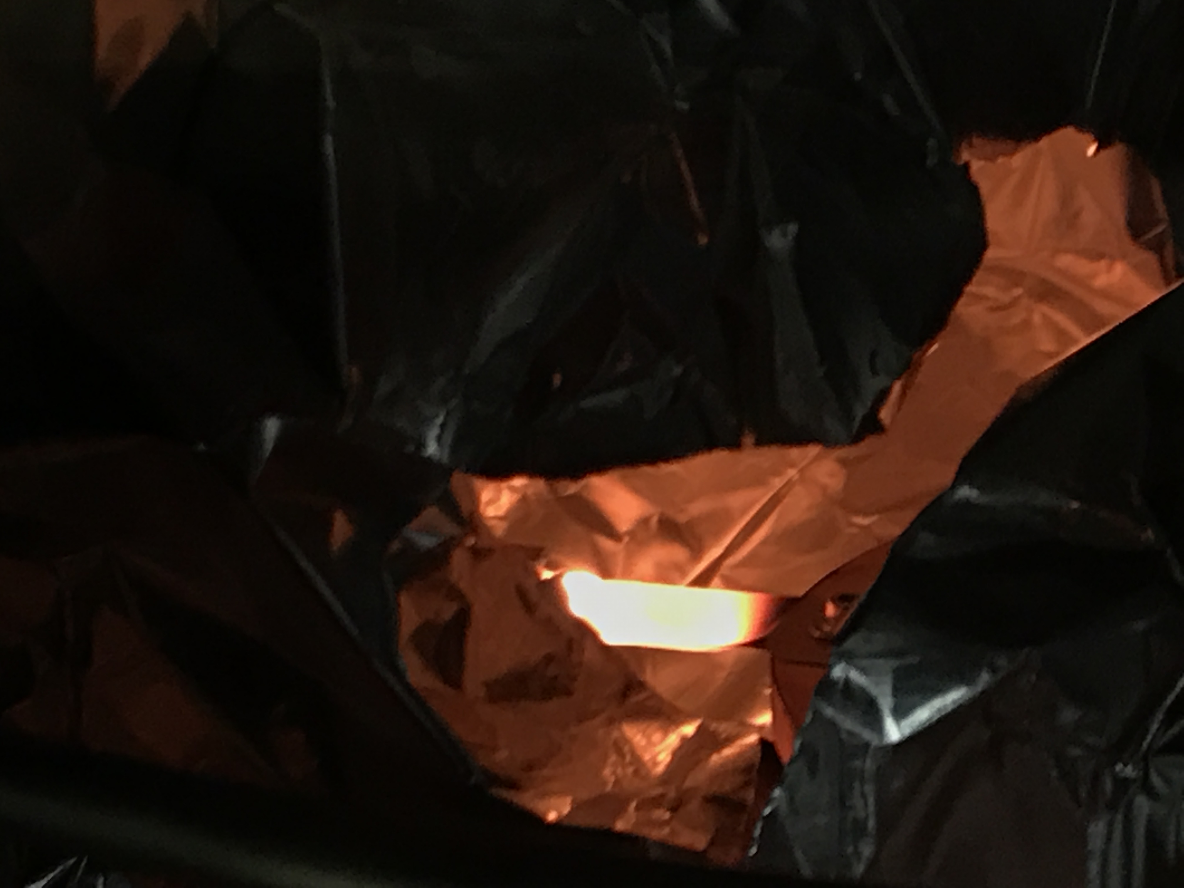
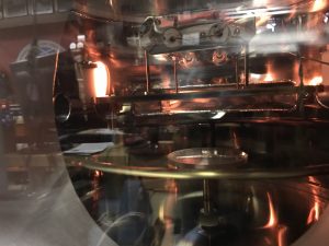
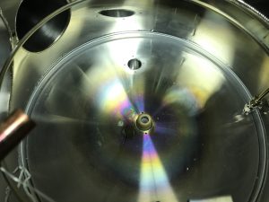
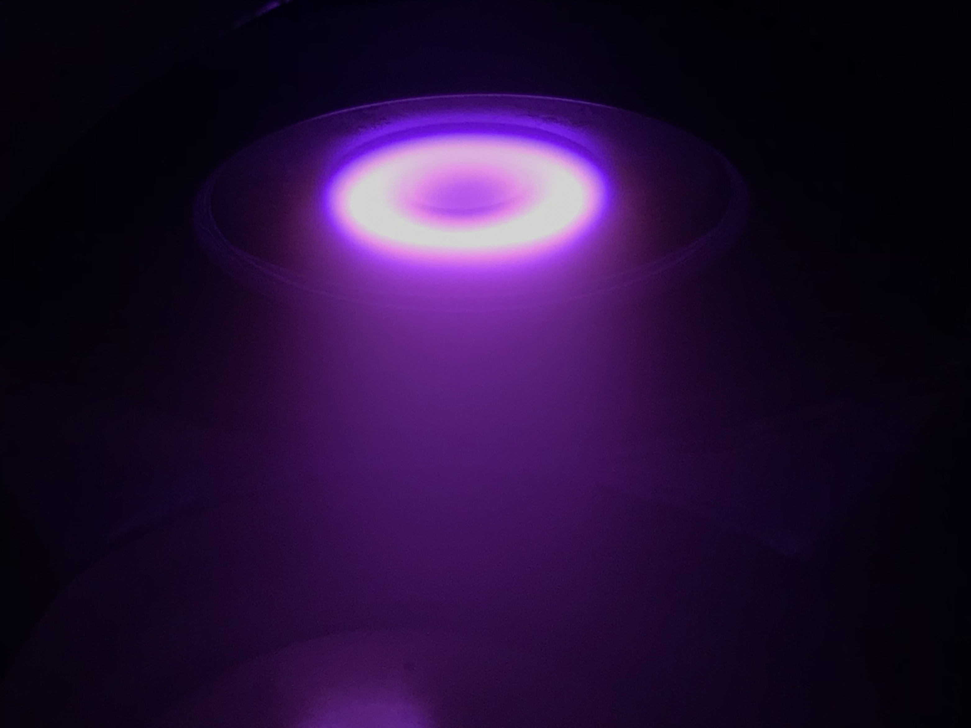
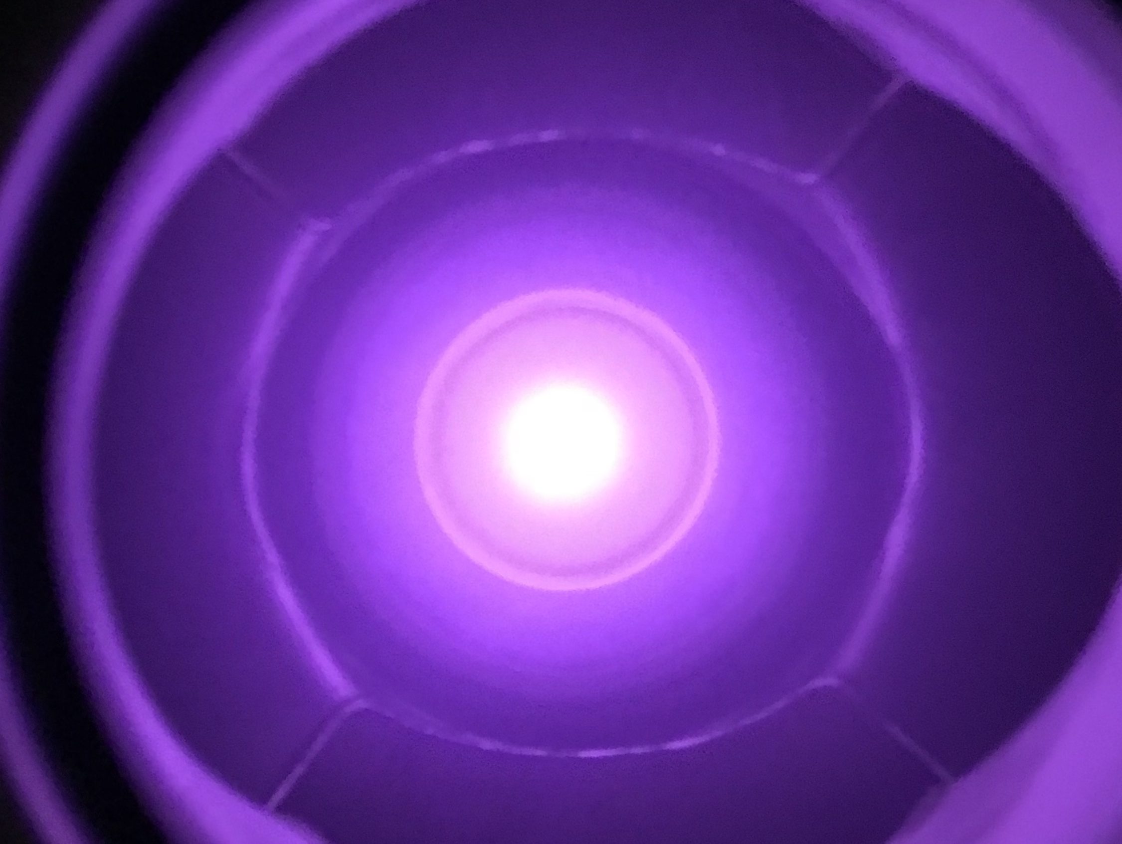
The “racetrack” ring-like plasma density in front of the target indicates the circular path of the electrons due to the Lorentz force, meaning that the magnet assembly has sufficient strength at the surface of the target.

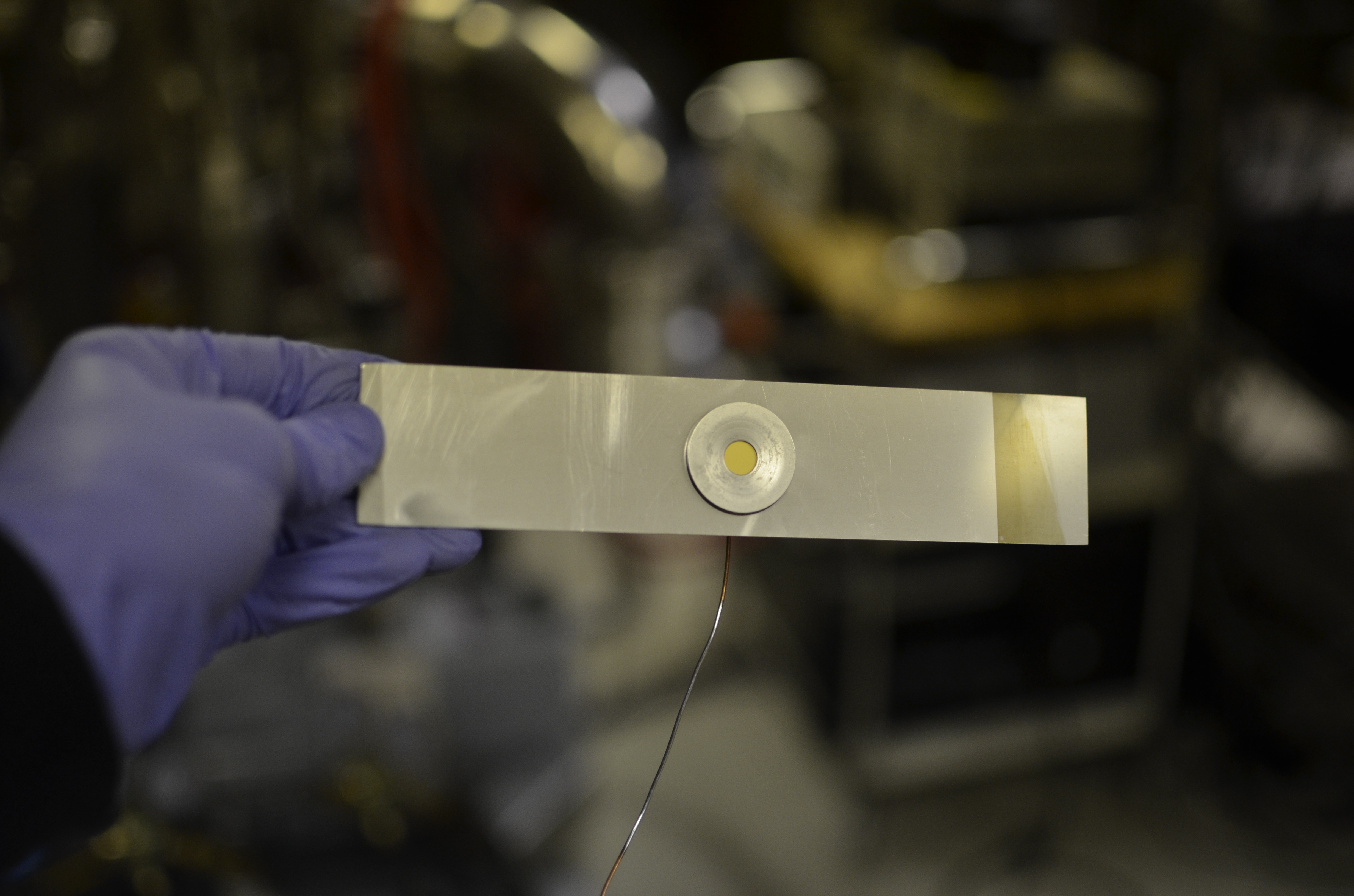
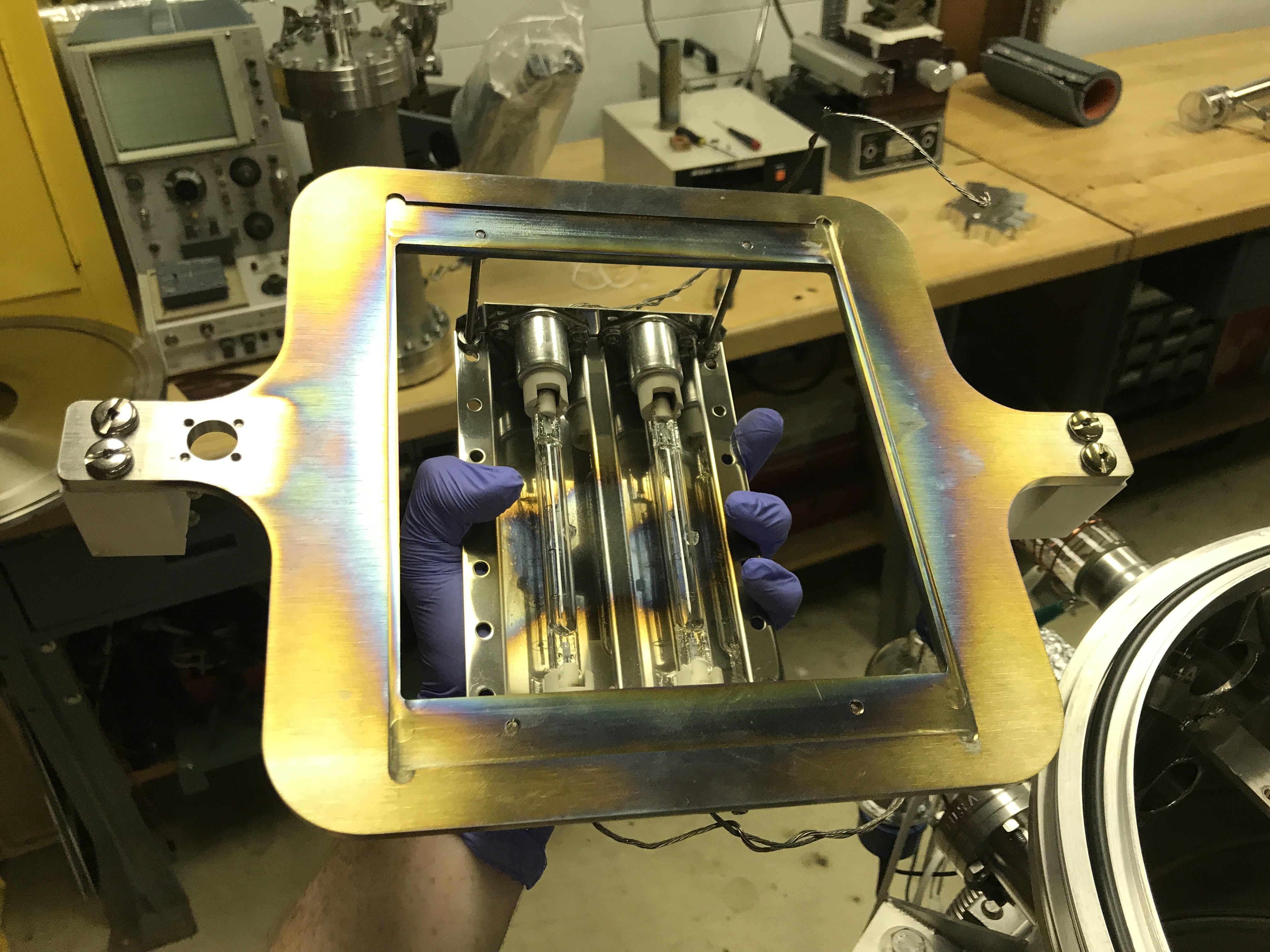
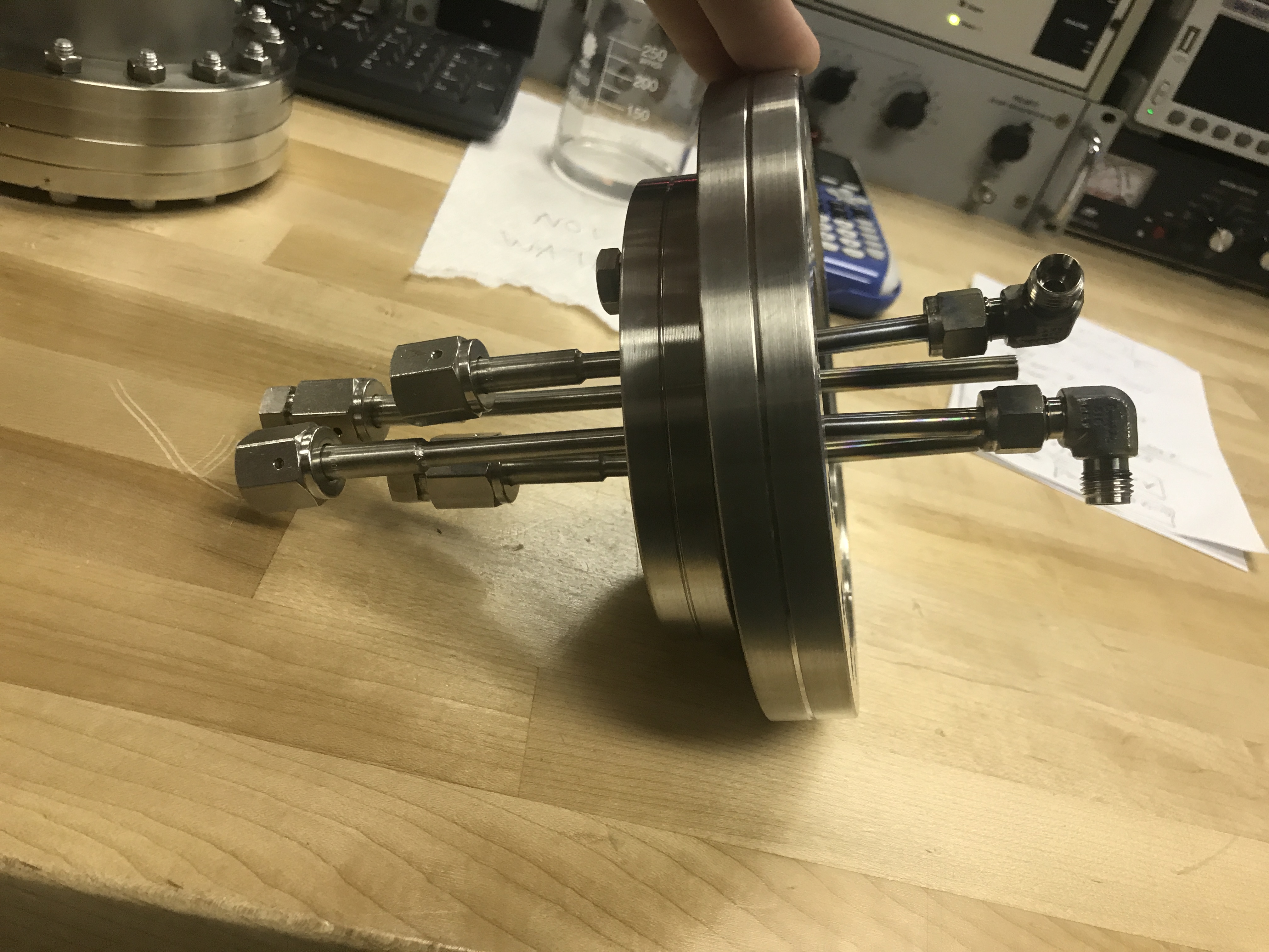
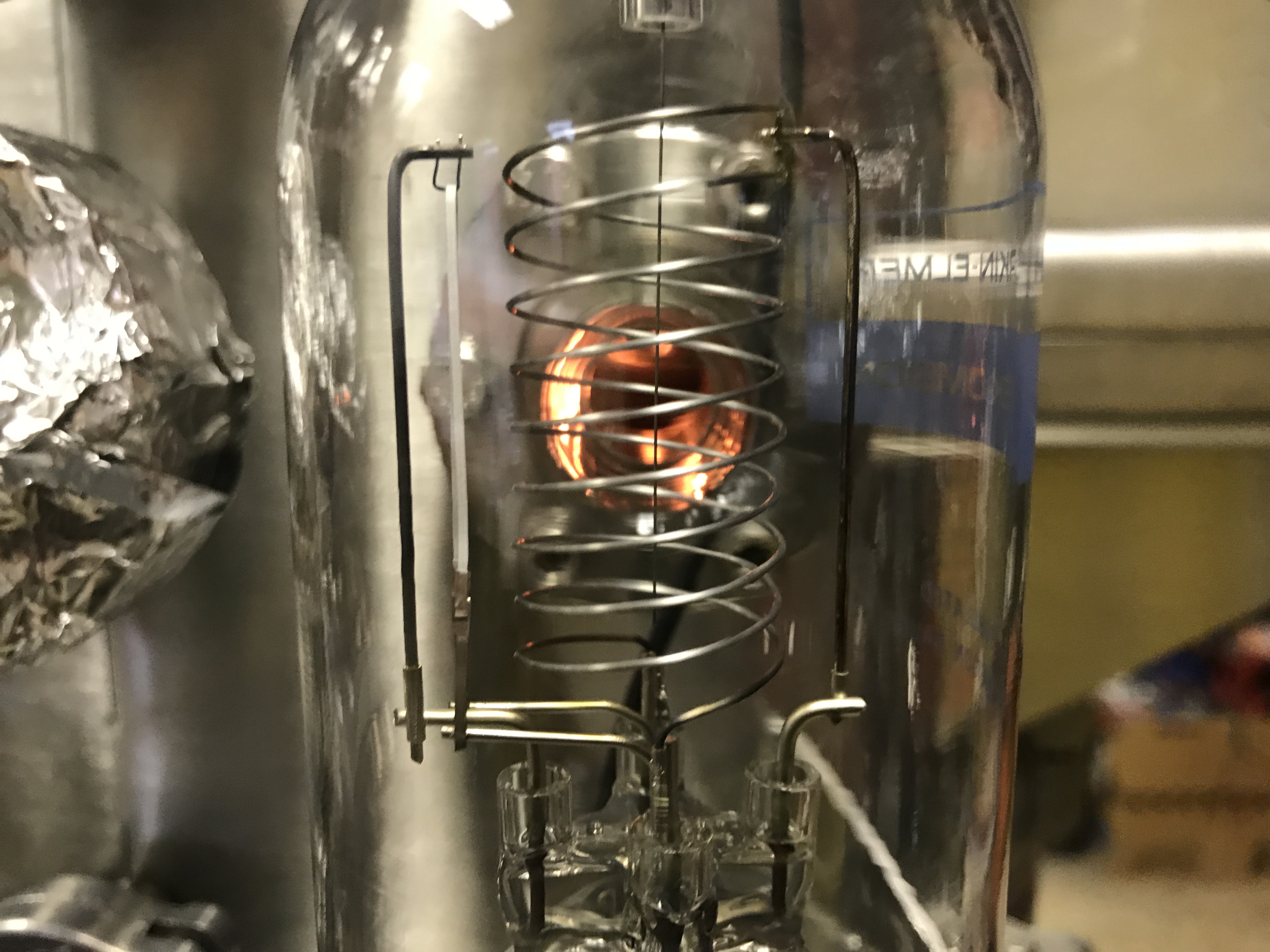
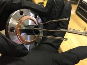
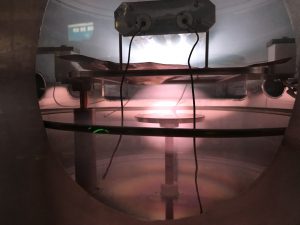
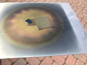
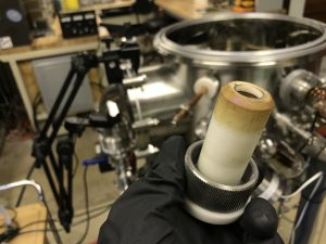
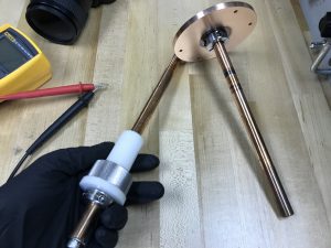
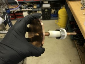
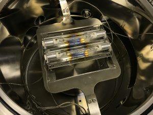
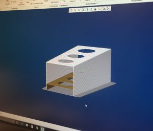
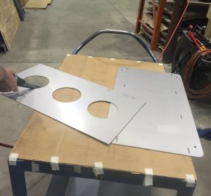
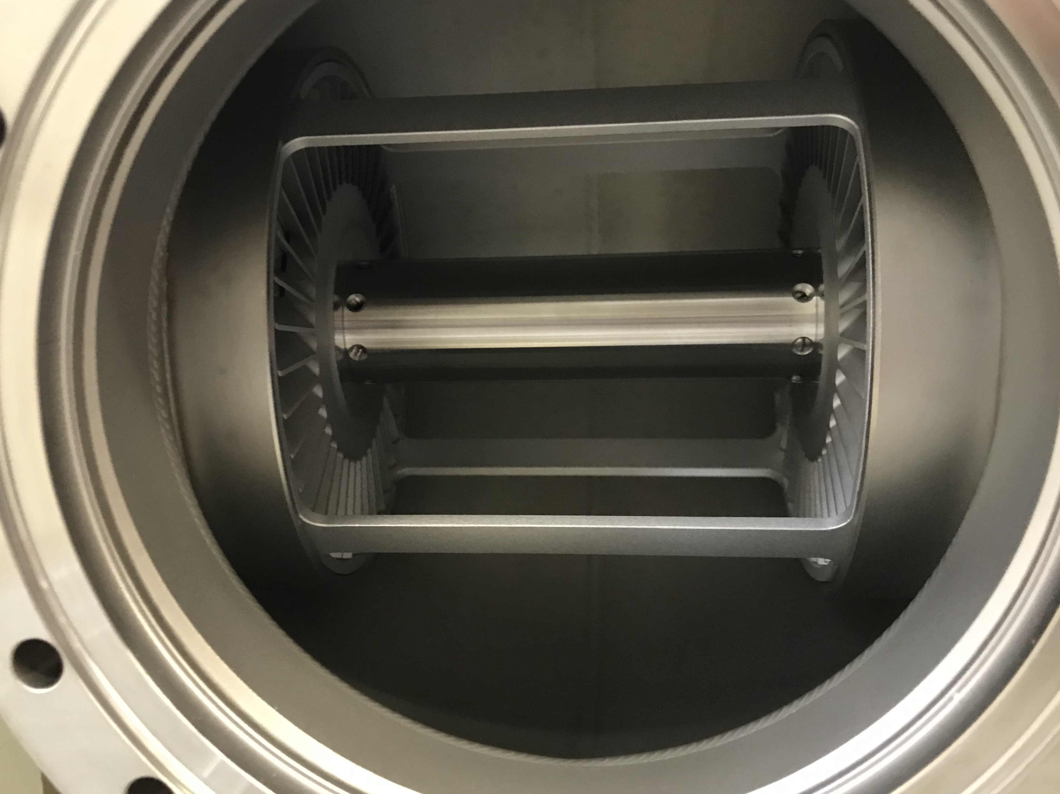
The final part of the project was the substrate heater which heats the sample from the back while it is being coated from the front. The specific process required that the substrate to be at elevated temperature (up to 850C) for 2 weeks. An infrared substrate heater was designed using 300W USHIO quartz lamps and a water cooled Aluminum parabolic reflector to focus the light onto the substrate.

Substrate heater
Substrate heater

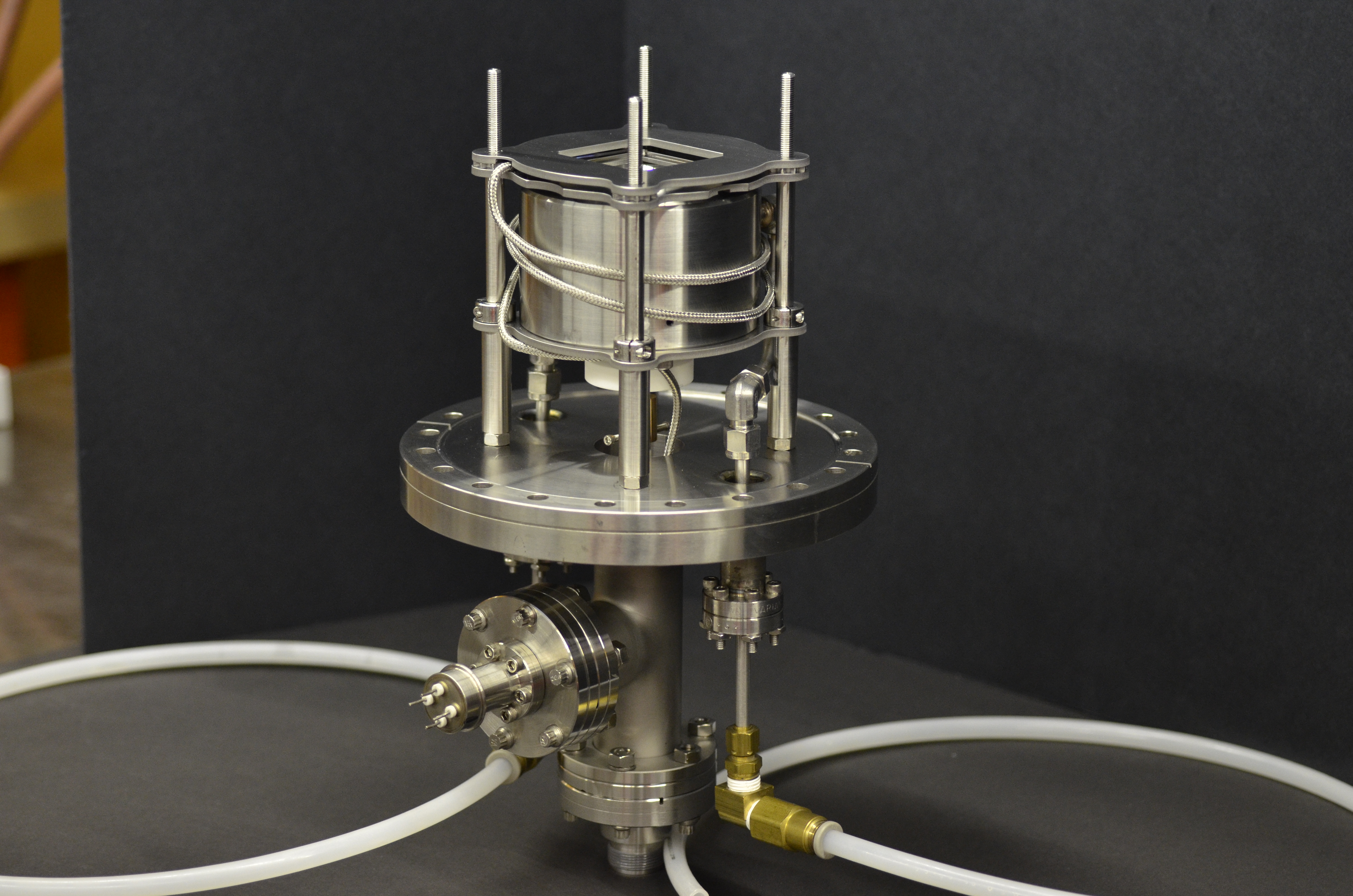
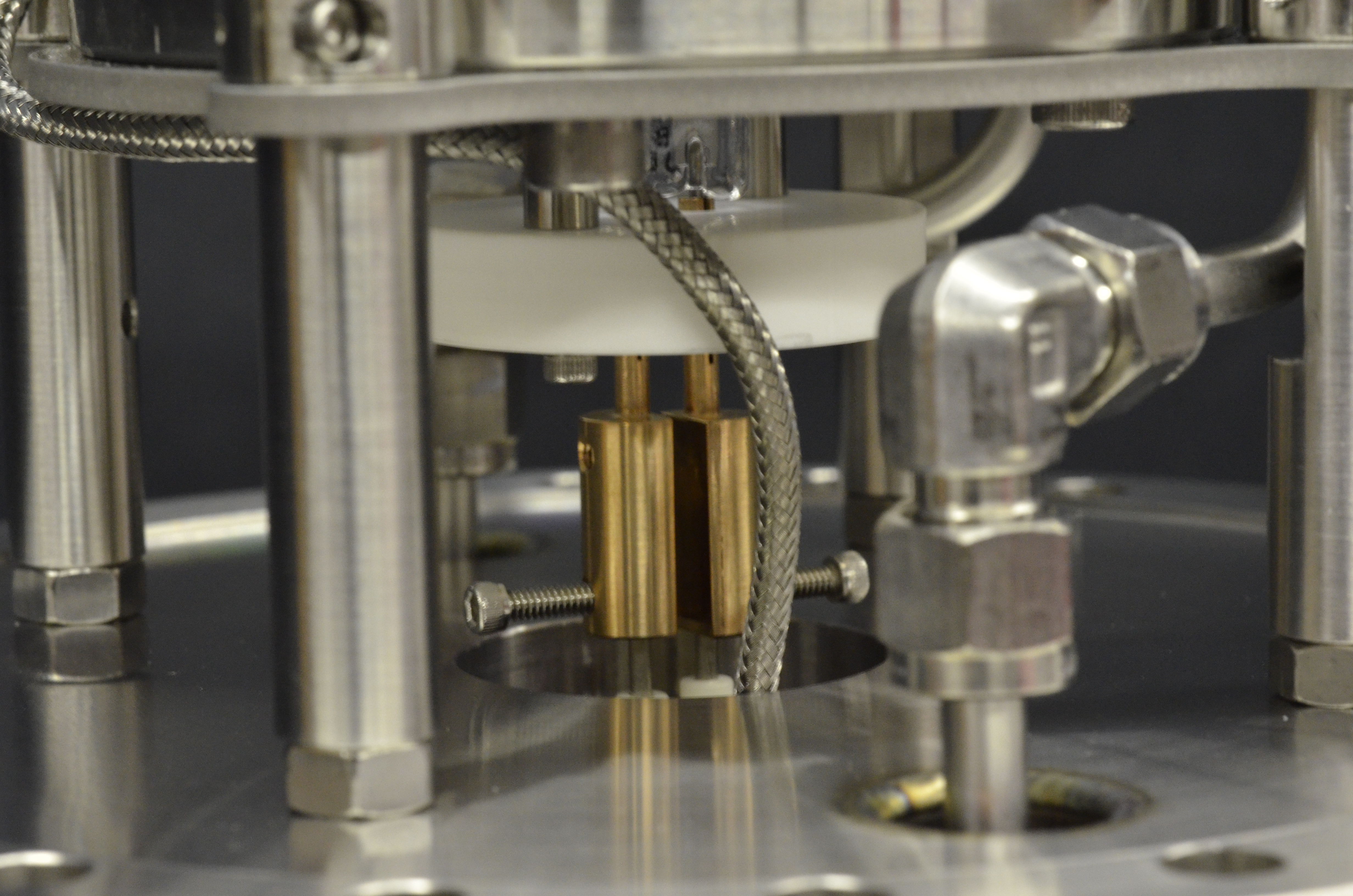
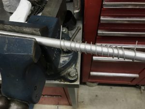
All parts of the heater which are exposed to elevated temperature are made from Inconel to avoid contamination of the delicate experiments. This includes the thermocouple, which is sheathed in Inconel and the wires are braided in Inconel as well.

Inficon Residual Gas Analyzer (Mass Spectrometer) Installation

An Inficon Transpector2 HPR RGA was purchased from eBay and refurbished. I will use it for leak checking and ion selection experiments. Thanks to Aota Vac and Inficon for software assistance!

Put simply, an RGA is a small mass spectrometer that allows the operator to see the composition of the residual gases left in the vacuum chamber after pumping. Basic theory here. 

This RGA is equipped with an electron multiplier so it operates at a maximum pressure of 1e-4Torr and is good down to about 1e-15Torr which is not a limit I will be reaching anytime soon. The spectra shown above indicates a large peak at an AMU of 18 which is H2O. This means that the chamber needs to be baked out to remove water embedded in chamber walls and surfaces until the highest peaks are N2 and O2.

A spectrum analyzer and near field probe was used to determine the main operating frequency of the RGA to approximately 3.02mhz. The RGA is also equipped with an Ar calibration source. Serial logs indicate that it was manufactured in 2007 and has been run thousands of hours past recommended service/filament replacement and the measured total pressure in the chamber was over an order of magnitude too high when compared to a hot-cathode ion gauge, but after calibration everything seems to be in spec.

Dual Source Thermal Evaporation + In Situ Plasma Cleaning

Thermal evaporation deposition of Al and Ge from Tungsten and Tantalum boats, respectively. A blind hole is drilled and tapped in the chamber bottom plate for a center tap feedthrough (common ground) for the boats. Deposition starts at around 7e-7Torr and ends around 5e-6Torr due to outgassing. Aluminum alloys with Tungsten at the high temperature and causes boat failure, a thicker gauge boat will be used in the future or one made of TiB2-BN or BN. Update: W 0.015″ boat thickness seems OK.

Approx. deposition rate throughout the run was 2.2A/s, with total accumulation of 500A. Much faster than my sputtering setup but yields a worse film.

In situ plasma cleaning is via the red ICP coil seen in the 8th picture. A Quartz Crystal Microbalance (QCM) is used to measure the thickness of the deposited films and current is supplied by a rewound microwave oven transformer. The UV-VIS spectrometer is used to monitor the emission spectra of O2 plasma. O2 is flowed into the chamber via a Mass Flow Controller (MFC) until the pressure is 75-100mTorr and the substrate is plasma cleaned for 5 minutes with 100W RF prior to depositions.

As current pass through the boats, they heat up to 1000 – 1800C and subsequently heat up much of the surrounding chamber and mounting parts. This starts serious outgassing in the chamber and without prior cleaning and bake out quickly raises the pressure to non-workable pressures and the deposition rate slows.

I added a second turbo pump to raise the pumping speed/gas throughput (previously 110L/s and now an additional 50L/s) and to tolerate higher outgassing.

It was also noted that the evaporation of Al with lots of H2O vapor in the chamber (no baking) leads to a reduction of chamber pressure (presumably the formation of Al2O3 with H2O) and the production of H2 as seen on an RGA.

Portable Plasma Research Chamber Construction

A small, modular, and versatile chamber was constructed for plasma and other research experiments. The main vacuum manifold can be configured with multiple feedthroughs in either standalone vacuum mode or connected to a large chamber. The front is a 6″ CF viewport that can be swapped for a gas feedthrough assembly.

The chamber is being used right now to study simulate vacuum conductance and pressure gradients across larger chamber systems such as an ion implanter with a turbo pump on one end and an ion source and MFC gas flow far away from the pump. The gas flow creates a higher pressure in the ion source chamber and, in theory, allows for low energy beam transport and acceleration into a much lower pressure substrate/target chamber (in the case of an ion implanter).

Conductance experiment

Titanium Sublimation Pump

A quick attempt making a titanium sublimation pump. Ti welding rod was bent into a coil around aluminum round stock and placed across 30-50 amps in high vacuum yielding successful results. Chamber was roughed down to 20mTorr then pumped with turbo to 1e-5 and briefly baked out. More testing will be done and results will be posted along with an updated design with shielding to make it into an actual pump rather than depositing all over the chamber walls.

Pumping Curve
Pumping Curve

During testing I experienced a strange pumping curve a few times as shown in the last picture where the filament while heated at 50 amps seemed to out gas twice before reaching sublimation.

(Click on image to enlarge)

The basic idea of a TSP or getter pump is that the filament is heated past 900 degrees c with a high current across it. The filament first out gases and raises the chamber pressure, but then reaches sublimation pressure where it begins to form a thin volatile coating of Ti on the chamber walls.

Titanium, in this heated state, will readily combine with gaseous specious in the chamber to form a more stable coating and the gas molecules in the chamber basically get incorporated into a thin film on the chamber walls and trapped. The filament current is cycled for highest effectiveness. A rewound MOT is used for high current supply.

UHV Bakeout and Ion Pump Operation

Two internal radiant infrared heat lamps and external resistive heating elements are used to bakeout the vacuum system for 24 hours allowing for ion pump operation. Normally when the chamber is full of unwanted moisture and impurities ionizing gas in the chamber will lead to a sharp increase in pressure due to plasma cleaning of the chamber walls and subsequent release of gas molecules.

Sputtering Setup V2

I machined a delrin insulator with fiberglass center rod for the CF 4 pin electrical feedthrough to provide power to the two incandescent substrate heaters in my new sputtering setup and to allow for instrumentation hookup.

New sputtering setup has dual substrate heaters as well as insulated feedthroughs for both target and substrate so that it can operate in DC, RF, Bias sputtering modes, or any combination therein. A quartz microbalance thickness monitor will be added soon.

The second to last image shows multiple colors in glow discharge during sputtering possibly due to DC bias. Bottom and top electrodes are both at different potentials with respect to chamber ground, so it is possible that different gasses are ionized due to differences in ionization energies of the residual gaseous species.

SEM Sample Preparation – DC Sputtering

Thin films of copper were prepared on non-conductive samples to be observed under the Electron Microscope. This process is called DC Diode Sputtering and took place at just below 100mTorr and 2000v @ 150watts.

materials-07-06377-g004-1024

This same setup can be used at lower powers to plasma clean or etch the top layer surface of the sample for better images under the SEM. Oxygen (and sometimes a small amount of Nitrogen) is usually a much more effective gas for this cleaning than Argon and leads to less unwanted sputtering as well.

Sputtering system v2 was made to support DC and RF sputtering so I can make dielectric coatings as well and it supports larger target and substrate samples. An insulator will be constructed to mount the target holder to the main chamber walls so that RF can be used more effectively.

(Click on image to enlarge)

SEM Demo

Miscellaneous Vacuum Chamber Upgrades

Miscellaneous Upgrades – Vent Valve/TC Gauge CF Tee Construction, Gas Cylinder Holder Fabrication, and Ion Gauge Controller Analog Output Hack

My HP (Granville Phillips)  hot cathode ionization gauge controller (59822b) had provisions for an analog output however the optional connector was not installed on the back panel and the connection points on the main PCB of the controller did not show any voltage deflection proportional to pressure so I took the pressure output from one of the stages in the electrometer which happened to be one of the outputs of a quad opamp chip. This output is fed to a NI DAQ USB6009 and displayed in a LabView VI so that the pressure of the chamber while pumping down can be held constant when requested by PID feedback loop with one or more of the mass flow controllers.

A pressurized gas cylinder holder was designed and fabricated by Diversatech Manufacturing, INC (www.diversatech.com) for safer operation of my vacuum chamber when using gasses such as Oxygen, Nitrogen, or Argon for processes such as sputtering or plasma cleaning.