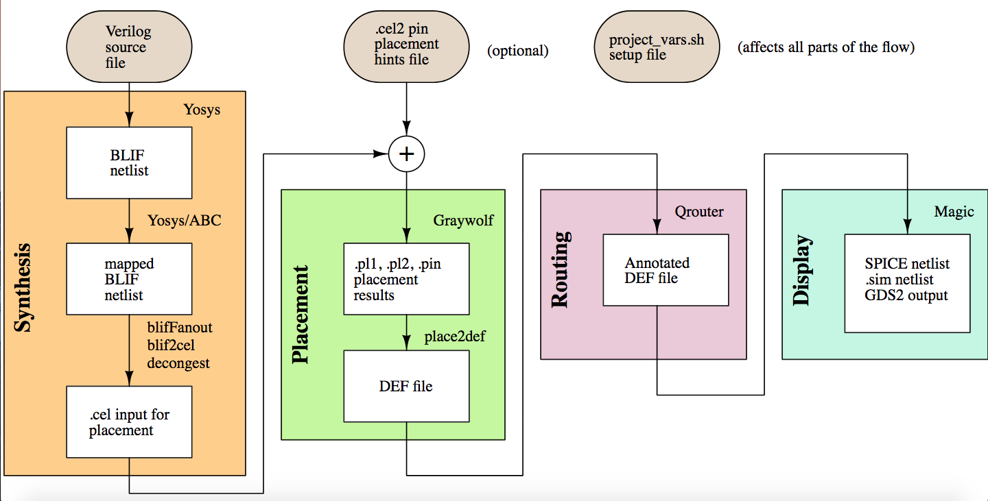
There are a number of open source layout and design tools for ICs however here I will just focus on Magic VLSI. Below are the steps to take a design from Verilog through synthesis and layout to the physical mask that is used for fabrication, via the Qflow digital synthesis flow.
The Verilog digital design for this example is a UART interface from www.asic-world.com and is synthesized/routed with the standard SCMOS rules, however a custom .tech file can be specified containing process details and design rules for DRC.


Once Qflow executes successfully, the design can be viewed in Magic after loading the appropriate cells and a GDS file is generated. This is opened in OwlVision GDSII Viewer or similar which can be used to generate the individual mask image files for each layer (active, poly, metal, etc.)
Using the same tools mentioned above, I also designed a simple PMOS chip to test my process. It is scalable to any reasonable size and contains 2 differential amplifier circuits (seen on right and middle) and a number of diodes/resistors and other test features on the left.


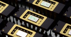
The design requires 4 masks for fabrication: active/diffusion, gate oxide, contact, and metal.


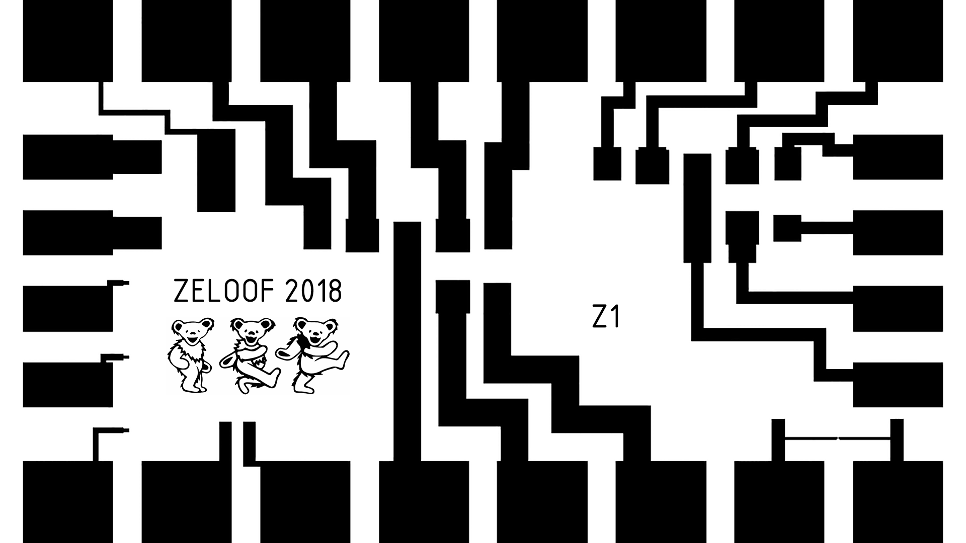
Fiducials should be added for subsequent layer alignment. Note: Grateful Dead bears are necessary for the circuit to function correctly.
good evening, could you send me the project “Photolithography Module”, I’m starting with CMOS, PMOS, NMOS, VHDL and TRANSISTOR in miniature.
Very nice. If you do again maybe add do centroid layout of diff pair and dummy’s to get better performance perhaps.
Hi,
Can I design & fabricate commercial grade SoCs from open source EDA tools (like Icarus &Magic) something like Using Risc-V ISA
It seems that Tim from opencircuitdesign.com made it with qflow. check this out:
http://opencircuitdesign.com/qflow/
Keep the good work! The series should be called bell labs at home :). Hope we can talk some day. Best regards.